Movable patch board based on sliding mechanism

A sliding mechanism and movable technology, which is applied to the parts, electrical components, coupling devices and other directions of the connecting device, can solve the problem of jack movement, etc., and achieve the effect of full utilization, simple structure, intelligent and efficient utilization

Inactive Publication Date: 2015-07-29
WUXI CITY CHONGAN DISTRICT TECH ENTREPRENEURSHIP SERVICE CENT
View PDF5 Cites 1 Cited by
  • Summary
  • Abstract
  • Description
  • Claims
  • Application Information

AI Technical Summary

Problems solved by technology

[0007] The technical problem to be solved by the present invention is to overcome the deficiencies of the prior art, provide a movable plug-in board based on a sliding mechanism, solve the problem that the existing plug-in board jack cannot move according to the size of the plug, and achieve plug-in Holes are removable for easy adjustment inside the power strip

Method used


Image

  • Movable patch board based on sliding mechanism
  • Movable patch board based on sliding mechanism

Examples


Embodiment 1

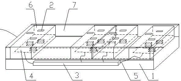
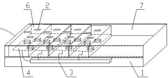
[0025] The socket board of this implementation includes a housing 1, a jack 2 and a control circuit board 3 connecting the jack 2, and also includes a sliding mechanism, the sliding mechanism is as follows: figure 1 As shown, it includes two slide rails 7, four jack shells 6, and 4 sets of interface circuits 4 for connecting the electric pieces inserted from the jack shells 6, wherein the jacks 2 are arranged in each jack shell 6 surface; the interface circuit 4 is fixedly arranged in each jack shell 6, and the interface circuit 4 is connected with the control circuit board 3 through the wire 5; the slide rail 7 is fixedly arranged on the inner wall of the housing 1, and each The jack shell 6 is slidably engaged on the slide rail 7 .

[0026] In this example, if figure 1 As shown, there are two slide rails 7, which are arranged on the inner wall of the housing 1 in parallel. There can be two slide rails 7 in the sliding mechanism, so that the two ends of the socket housing 6...

Embodiment 2

[0028] The socket board of this implementation includes a housing 1, a jack 2 and a control circuit board 3 connecting the jack 2, and also includes a sliding mechanism, which includes a slide rail 7, four jack shells 6 and a Connect 4 groups of interface circuits 4 that are inserted into electric sheets from the jack shell 6, wherein the jack 2 is arranged on the surface of each jack shell 6; the interface circuit 4 is fixedly set in each jack shell 6, and the The interface circuit 4 is connected to the control circuit board 3 through wires 5 ; the slide rail 7 is fixedly arranged on the inner wall of the housing 1 , and each jack shell 6 is slidably clamped on the slide rail 7 . Different from the above-mentioned embodiments, the surface of the jack shell 6 is arranged with three-pin jacks and two-pin jacks, and the number is not limited to the number in the figure. Users can feel that the surface of the jack shell 6 covers Number and orientation of jacks. Therefore, the sp...


PUM


Abstract

The invention discloses a movable patch board based on a sliding mechanism. The movable patch board comprises a shell (1), jacks (2), a control circuit board (3) and the sliding mechanism. The control circuit board (3) is connected with the jacks (2). The sliding mechanism comprises a sliding rail (7), a plurality of jack shells (6) and interface circuits (4). The interface circuits (4) are used for switching on electrical sheets inserted from the jack shells (6). The jacks (2) are formed in the surface of each jack shell (6). The interface circuits (4) are fixedly arranged in the jack shells (6) respectively and are connected with the control circuit board (3). The sliding rail (7) is fixedly arranged on the inner wall of the shell (1). Each jack shell (6) is fastened to the sliding rail (7) slidably. The movable patch board has the advantages that each jack shell becomes an independent shell, distances among the jack shells can be adjusted to avoid mutual influences of inserted plugs, space of the shell is utilized fully, and the patch board is simple and convenient in structure and can be utilized efficiently.

Description

technical field [0001] The invention relates to a movable plug-in board based on a sliding mechanism, which belongs to the technical field of basic electrical components. Background technique [0002] The wiring board is a kind of socket, which is a porous socket formed by putting multiple sockets together. Simply put, a power strip socket refers to a movable porous socket with a power cord and a plug, which is a common name for a power converter. [0003] The traditional plug-in board includes a shell and a control circuit board, and a plurality of jacks are arranged on the shell, and the jacks are respectively connected to the control circuit board, thereby supplying power. The number of jacks in the plug-in board is large, so that the socket can be used in one socket. Multi-purpose, space-saving, line-saving, simple and practical, it is a necessity of life. Especially nowadays, the widespread use of electrical equipment has led to the widespread use of power strips, mak...

Claims


Application Information

Patent Timeline
Patent Type & Authority Applications(China)
IPC IPC(8): H01R13/514H01R27/02
Inventor 叶飞潘琳顾肖红
Owner WUXI CITY CHONGAN DISTRICT TECH ENTREPRENEURSHIP SERVICE CENT
Why Eureka
Try Eureka