
Low-loss network type optical receiver and control method

An optical receiver, low-power technology, applied in the field of low-power network optical receiver and control, can solve the problems of complex network management equipment, unreliable performance, inconvenient construction and debugging, etc., to achieve remote management, construction The effect of convenient debugging and wide optical power acceptance range

Inactive Publication Date: 2015-07-29
上海新纳通信技术有限公司
View PDF6 Cites 2 Cited by
  • Summary
  • Abstract
  • Description
  • Claims
  • Application Information

AI Technical Summary

Problems solved by technology

Existing traditional optical receivers generally have problems such as small receiving range, simple power display, uncontrollable output level, too many plug-ins, inconvenient construction and debugging, inconvenient remote management, no remote control function, and unreliable performance. Influence the development and application of HFC network
The performance of the traditional radio frequency modulation HFC network management system is unstable, the investment in front-end equipment is large, the network management equipment is complex, and the requirements for network construction are high

Method used


Image

  • Low-loss network type optical receiver and control method
  • Low-loss network type optical receiver and control method

Examples


Embodiment Construction

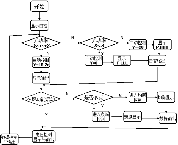
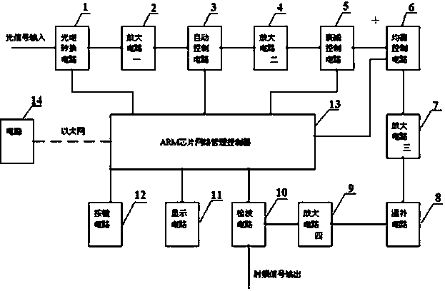
[0017] like figure 1 The schematic block diagram of the structure of the low-power network optical receiver shown in the figure includes photoelectric conversion circuit 1, amplifying circuit 1, automatic control circuit 3, amplifying circuit 2 4, attenuation control circuit 5, equalization control circuit 6, and amplifying circuit 3 7 , temperature compensation circuit 8, amplifier circuit 4 9, level detection circuit 10, also includes power module, display circuit 11, button circuit 12, ARM chip network management controller 13, Ethernet, computer 14.

[0018] The power module is used to provide 12V, 8V, 5V, 3.3V DC voltage. Provides power to individual circuits and chips.

[0019] The optical signal is input to the photoelectric conversion circuit 1 through the optical cable, and the photoelectric conversion of the photoelectric conversion circuit 1 is converted into a suitable, low-noise, and signal-flat electrical signal output; the output signal enters the amplifying ci...


PUM


Abstract

The invention relates to a low-loss network type optical receiver and a control method thereof. The low-loss network type optical receiver successively comprises a photoelectric conversion circuit, a first amplification circuit, an automatic control circuit, a second amplification circuit, an attenuation control circuit, an equalization control circuit, a third amplification circuit, a temperature compensation circuit, a fourth amplification circuit and a level demodulation circuit, and further comprises a power supply module, a display circuit, a button circuit, an ARM chip network management controller, an Ethernet network and a computer, wherein the photoelectric conversion circuit, the level demodulation circuit and the button circuit input signals to the ARM chip network management controller, the ARM chip network management controller outputs control signals to the automatic control circuit, the attenuation control circuit and the equalization control circuit, the circuits employ low-loss chips, the amplification circuits realize multistage amplification, the heating capacity of a product is reduced, and the service life of the product is prolonged. The optical power receiving scope is large, the output level is controllable, the construction debugging is convenient, the operation state of equipment can be monitored in real time, and remote management can be realized.

Description

technical field [0001] The invention relates to an optical receiver, in particular to a low power consumption network optical receiver and a control method. Background technique [0002] With the development of "three-network integration", that is to realize the integration of business applications of the three major networks of telecommunication network, computer network and broadcasting network. With the development and changes of policy, external environment, user demand and communication technology, the development of a series of value-added services such as VoD and VoIP has also been put on the agenda while cable operators have launched broadband services one after another. For cable operators, if they still rely on manual network management, it will not only take a long time to repair, but also be very passive in management. Therefore, how to realize the automatic management of the network, discover hidden problems in advance and repair them in time has become a new t...

Claims


Application Information

Patent Timeline
Patent Type & Authority Applications(China)
IPC IPC(8): H04B10/69H04B10/07
Inventor 张春生鲁亮
Owner 上海新纳通信技术有限公司
Learn More