
Device and method for producing semifinished products for wind power system rotor blades and rotor blade and wind energy system produced therewith

A technology for rotor blades and wind energy equipment, applied to equipment for manufacturing semi-finished products for wind energy equipment rotor blades and, thereby, the field of rotor blades and wind energy equipment, capable of solving problems such as not being eliminated, and reducing logistical costs , the effect of optimizing the structure

Active Publication Date: 2015-07-29
WOBBEN PROPERTIES GMBH
View PDF6 Cites 5 Cited by
  • Summary
  • Abstract
  • Description
  • Claims
  • Application Information

AI Technical Summary

Problems solved by technology

But the disadvantages found in the prior art are not eliminated here

Method used


Image

  • Device and method for producing semifinished products for wind power system rotor blades and rotor blade and wind energy system produced therewith
  • Device and method for producing semifinished products for wind power system rotor blades and rotor blade and wind energy system produced therewith
  • Device and method for producing semifinished products for wind power system rotor blades and rotor blade and wind energy system produced therewith

Examples


Embodiment Construction

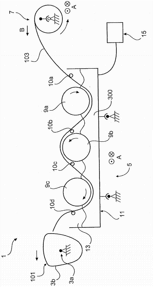
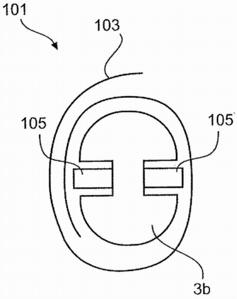
[0051] exist figure 1 An apparatus for manufacturing blade tips according to a preferred embodiment of the present invention is schematically depicted in . The device 1 has a winding mandrel 3a, which is rotatably driven. Fastened to the winding mandrel 3 a is a winding casing 3 b around which the fiber composite material 103 is wound up in a track. The winding mandrel 3a is arranged stationary.

[0052] The device 1 also has a soaking device 5 . The soaking device 5 has a soaking tub 13 with a bottom 11 . A plurality of deflection rollers 9a, b, c are arranged in the infusion device 5 in a spaced manner from the bottom. as indicated in figure 1 As shown in , the distances of the deflection rollers 9 a - c from the base 11 can be chosen to be the same or different depending on which angle the fiber composite material 103 is wound around the deflection rollers 9 a , b , c. Furthermore, the soaking device 5 has a plurality of tensioning rollers 10a, b, c, d, which act on t...


PUM


Abstract

The invention relates to a device (1) for producing blade end semifinished products (101) for wind power system rotor blades (100), with a winding mandrel (3a), which can be rotated to wind up preferably strip-shaped, fibre composite material. According to the invention it is proposed that an impregnation system (5) which can be traversed along the winding mandrel for the impregnation of the fibre composite material before rewinding around the winding mandrel is a magazine device (7) for providing the fibre composite material which can be moved along the winding mandrel, preferably synchronously with the impregnation device.

Description

technical field [0001] The invention relates to a device for producing blade ends for rotor blades of wind energy installations, said device having a winding mandrel which is rotatable for winding up a preferably ribbon-shaped fiber composite material . Background technique [0002] Basically, in the technical field of rotor blades, and especially in the technical field of rotor blades of wind energy installations, special stability requirements are imposed on the hub-side end parts of the rotor blades, since these end parts are responsible for the introduction of forces from the blades. into the hub and is subjected to particularly high static and dynamic loads. It is therefore important that blade ends for rotor blades of wind energy installations can be produced with high production accuracy and while maintaining high quality standards. [0003] Blade ends for the aforementioned rotor blades are generally constructed from a plurality of components, at least some of whic...

Claims


Application Information

Patent Timeline
Patent Type & Authority Applications(China)
IPC IPC(8): B29C53/56B29C53/80B65H49/00B65H69/06B29C70/38F03D1/06B29L31/08
CPCB29L2031/085Y02E10/721B65H49/32B29C70/32B29C53/8066B29C53/56F03D1/0675B29C53/8016F03D13/20Y02E10/728Y02P70/10B29C53/82B29C70/36B65H49/00B65H69/06Y02E10/72Y02P70/50B29C70/021B29D99/0028B29L2031/08
Inventor 亚历山大·霍夫曼彼得·弗里德延斯·耶贝斯弗兰克·克诺普
Owner WOBBEN PROPERTIES GMBH
Learn More