Injecting molding method of thermal plastic resin product and mold used thereof

A thermoplastic resin and injection molding technology, which is applied in the field of injection molding of thermoplastic resin products and the molds used, can solve the problems of complex mold structure, reduce mold production costs, etc., achieve easy molding process, realize molding time, and glossiness. improved effect

Inactive Publication Date: 2007-08-01
宗形株式会社
View PDF2 Cites 3 Cited by
  • Summary
  • Abstract
  • Description
  • Claims
  • Application Information

AI Technical Summary

Problems solved by technology

As a solution, install a seal or the like in the combined part of the mold to seal, but the structure of the mold becomes complicated, which becomes an obstacle to reduce the cost of mold manufacturing

Method used


Image

  • Injecting molding method of thermal plastic resin product and mold used thereof
  • Injecting molding method of thermal plastic resin product and mold used thereof
  • Injecting molding method of thermal plastic resin product and mold used thereof

Examples


Embodiment 1

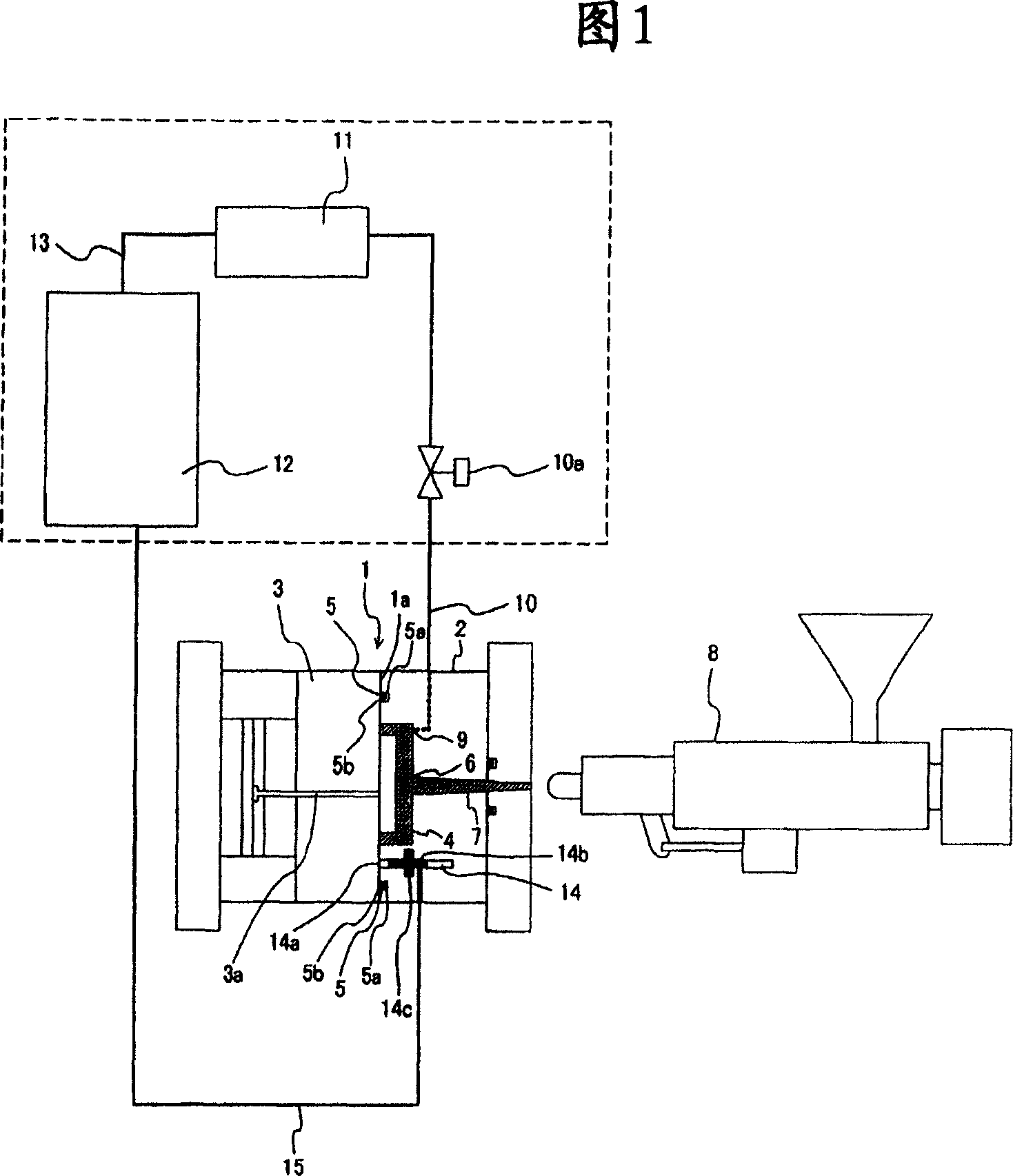
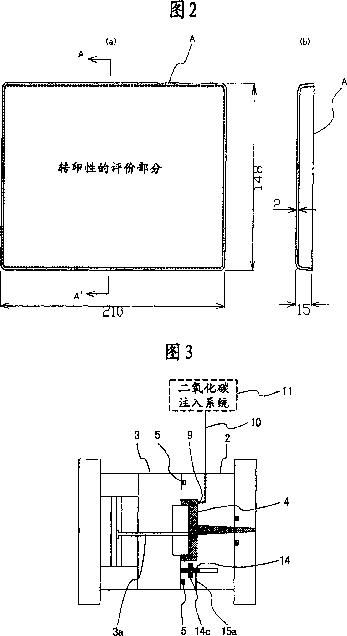
[0067] Figure 1 shows the molding method of the present invention for improving transferability and glossiness and its implementation in a mold. In this Fig. 1, 1 is a mold, and the mold 1 is composed of a fixed side mold 2 and a movable side mold 3, and a cavity 4 is formed when the molds are closed.

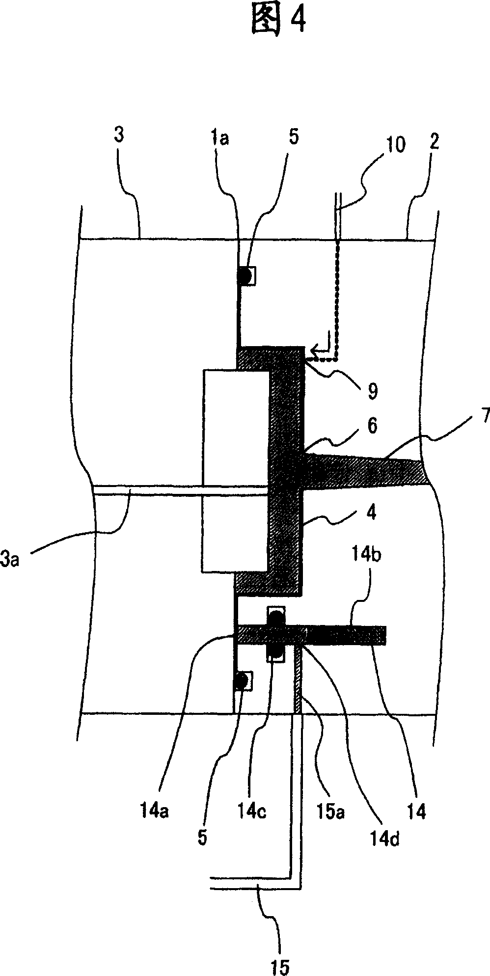
[0068] 5 is a sealing mechanism provided on the joint surface 1a to surround the above-mentioned cavity 4, the sealing mechanism 5 is composed of a sealing material mounting groove 5a formed on the fixed side mold 2, and a rubber sealing material 5b mounted in the mounting groove 5a. constitute.

[0069] 6 is the gate of the above-mentioned cavity 4, 7 is the runner connected to the gate 6, and 8 is a screw type resin filling machine for filling resin into the cavity 4 from the above-mentioned runner 7 through the gate 6.

[0070] 9 is a fluid injection port provided on the cavity surface of the fixed side mold 2 in the above-mentioned cavity 4, 10 is a fluid injection pipe co...

Embodiment 2

[0076] The structure of this embodiment 2 is: in order to prevent the air discharged from the cavity 4 from being hindered by the sealing mechanism 5 when filling the resin, the pressure in the cavity 4 and the pressure of the filled resin are higher than the specified pressure, as shown in Figure 5 The air groove 16 is formed in the fixed side mold 2, and the air discharged from the cavity 4 is temporarily accommodated in the air groove 16, so that the air can be discharged from the cavity 4 while preventing the resin pressure from increasing.

[0077] The above-mentioned Examples 1 and 2 are examples of improving the transferability and glossiness by using carbon dioxide. The operation examples when various fluids are used to modify the visible surface of the molded article can be carried out through the same process as the above-mentioned carbon dioxide injection method. forming.

Embodiment 3

[0081] The third embodiment is an example in which a sealing mechanism 5 is provided on the movable side mold 3 as shown in FIG. 6 and an example in which a sealing mechanism 5 is provided on the fixed side mold 2 as shown in FIG. 7 . In this way, any sealing mechanism 5 may be used, but it is preferable to install it on the non-movable fixed-side mold 2 .


PUM

PropertyMeasurementUnit
glossaaaaaaaaaa

Abstract

In the injecting molding method of carbon dioxide and other fluids, the transfer printing performance and glossiness are excellent, it can save consumption of consumed fluid. The junction surface of fixing side die 2 surrounding the cavity 4 and the movable side die 3 is equipped with sealing device 5, the die of retracting device is installed between the sealing device 5 and the cavity 4 and the retracting device is used for recoveries the injecting fluid of cavity which flows out of said junction surface; first locking the die tightly, second filtering resin into cavity 4, then injecting fluid used for modifying the visible surface between the visible surface of product in cavity 4 and the cavity 4 surface contacting with the visible surface, such as carbon dioxide, and then increasing resin pressure to make the visible surface is closed with the cavity 4 surface, completing the injecting shaping after pressure maintaining and cooling. The recycling fluid can be used again.

Description

technical field [0001] The present invention relates to the injection molding method of thermoplastic resin and the mold used therefor, in particular, to the injection molding of thermoplastic resin used to improve the transfer and glossiness of the visible surface of the product, or to modify the visible surface The method and the molds it uses. technical background [0002] Generally, injection molding of thermoplastic resin is a process of filling molten resin into a mold cavity, cooling in the mold, and obtaining a molded product, but in this injection molding, since the mold is kept at a temperature lower than that of the resin before the resin is filled Therefore, the resin solidifies from the moment the molten resin is filled into the cavity, and a layer in the middle of curing called the skin layer is formed on the surface. In particular, with fountain flow, although the flow front of the molten resin is transferred to the surface of the molded product, solidificati...

Claims


Application Information

Patent Timeline
Patent Type & Authority Applications(China)
IPC IPC(8): B29C45/57B29C45/17B29C45/26B29C45/76
Inventor 土屋淳志馆山弘文
Owner 宗形株式会社
Why Eureka
Try Eureka