Injection molding method and device

An injection molding device and injection molding technology, applied in the field of injection molding devices, can solve the problems of long molding time, non-uniform coverage of the terminal part of the mold cavity, curing, etc., shorten the molding time, improve transferability, and eliminate deformation Effect

Inactive Publication Date: 2009-05-06
FUJISEIKO
View PDF1 Cites 5 Cited by
  • Summary
  • Abstract
  • Description
  • Claims
  • Application Information

AI Technical Summary

Problems solved by technology

[0004] However, the melted synthetic resin moves in the cavity while being cooled, so it may not evenly spread to the terminal part of the cavity, especially when the thickness of the molded product becomes thinner, it may flow. There is a problem that the melted synthetic resin is solidified, and the molding time is long because the inductor for high-frequency induction heating, for example, is sandwiched between the fixed mold and the moving mold to vibrate.

Method used


Image

  • Injection molding method and device
  • Injection molding method and device
  • Injection molding method and device

Examples


Embodiment Construction

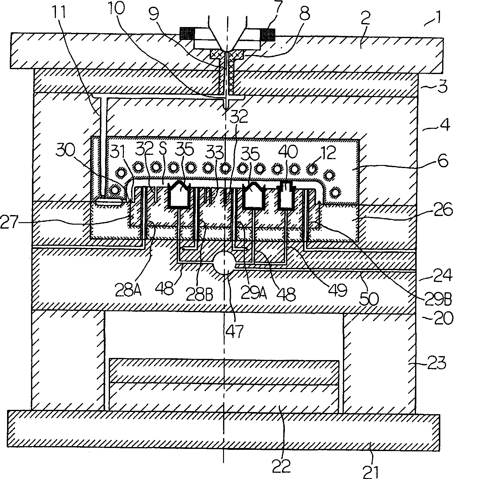
[0138] Embodiments of the present invention will be described below with reference to the drawings. First, according to figure 1 Next, the overall configuration of the injection molding apparatus will be described. 1 is a fixed-side assembly mounted on a fixed platen (not shown) by screws. The fixed-side assembly 1 includes: a first bottom plate 2 on a fixed side; a second bottom plate 3 on a fixed side. fixed on the first bottom plate 2 on the fixed side; the third bottom plate on the fixed side is fixed on the second bottom plate 3 on the fixed side by screws; the female mold part (fixed mold part) 6 is arranged on the fixed side In the recess of the third bottom plate 4 and fixed on the third bottom plate 4 of the fixed side by screws; the positioning ring (locate ring) 7 is arranged on the first bottom plate 2 of the fixed side and leans against the fixed platen. The position is to position the first bottom plate 2 on the fixed side relative to the fixed platen; and a sp...


PUM


Abstract

In an injection moulding method, vapor is supplied in a thermal medium channel of master mould. The mould is closed after heating a mould cavity forming side of master mould part for raising the temperature of mould cavity forming side. The temperature raising is stopped after the mould cavity forming side obtains a preset temperature, and melted synthetic resin J with a preset amount is injected into the mould cavity S. Afterwards, pressurized gas is injected between the back surface of synthetic resin J and the cavity forming surface of male mould part. The surface of synthetic resin J is pressed to the mould cavity forming surface for maintaining pressure. The pressure is maintained while cooling water is started to feed into the heat medium channel for hardening the synthetic resin on the surface of master mold. When the synthetic resin is hardened to a certain degree, the injection of pressurized gas is stopped, and furthermore the pressurized gas is discharged out of the device. Cold gas is injected between the back surface of synthetic resin and the mould cavity forming surface of male mould part when the discharging of pressurized gas to the outside is finished. Lastly the mould is opened when the synthetic resin is hardened to a degree that the synthetic resin can be taken out.

Description

Technical field: [0001] The invention relates to an injection molding method and an injection molding device. More specifically, the present invention relates to an injection molding method and an injection molding apparatus in which pressurized gas is injected between a synthetic resin in a cavity and a cavity forming surface. Background technique: [0002] Conventionally, for example, as disclosed in Patent Document 1, etc., there has been proposed a technique of improving transferability by heating the surface-side cavity-forming surface on which the surface side of a molded product is molded before injecting molten synthetic resin. . [0003] [Patent Document 1] Japanese Patent Laid-Open No. 6-254924 [0004] However, the melted synthetic resin moves in the cavity while being cooled, so it may not evenly spread to the terminal part of the cavity, especially when the thickness of the molded product becomes thinner, it may flow. There is a problem that the melted synthe...

Claims


Application Information

Patent Timeline
Patent Type & Authority Applications(China)
IPC IPC(8): B29C45/57B29C45/73B29C45/17B29C45/26
CPCB29C45/174B29C45/46B29C45/57
Inventor 横山勝助金子光雄
Owner FUJISEIKO
Why Eureka
Try Eureka