Automatic locking safety pin

An automatic locking and safety pin technology, applied to quick-action fasteners, bolts, etc., can solve the problems of being difficult to replace, easily causing accidents, time-consuming and labor-intensive, etc., and achieve the effect of easy replacement, less accidents, and easy manufacturing

Inactive Publication Date: 2015-08-05
MCC SFRE HEAVY IND EQUIP
View PDF5 Cites 8 Cited by
  • Summary
  • Abstract
  • Description
  • Claims
  • Application Information

AI Technical Summary

Problems solved by technology

[0003] The purpose of the present invention is to provide an automatic locking safety pin, which solves the problem of manual operation in the prior art, which is time-consuming and labor-intensive, and is not easy to replace. If it is not in use and forgets to insert the pin seat, it will easily cause accidents.

Method used


Image

  • Automatic locking safety pin
  • Automatic locking safety pin
  • Automatic locking safety pin

Examples


Embodiment Construction

[0016] The present invention will be described in detail below in conjunction with the accompanying drawings and specific embodiments.

[0017] The description in the following text takes the pin in the vertical position as an example, and the position in actual use can be deduced by analogy.

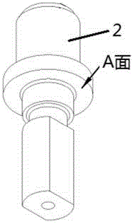
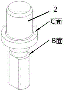
[0018] refer to figure 1 , figure 2 , the structure of the safety pin main body 2 of the present invention is that the main body of the safety pin main body 2 is a multi-layer stepped pin, which is successively a cylinder, a convex cylinder, a thin cylinder, a thin neck, and a beveled cylinder from top to bottom, wherein the convex cylinder The lower end surface (A surface) of the body is the spring matching surface, the upper end surface (C surface) of the convex cylinder is the locking position positioning surface, and the upper end surface (B surface) of the beveled cylinder is the loosening position positioning surface.

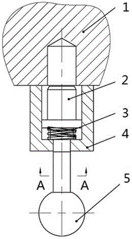
[0019] refer to image 3 The overall structure of the aut...


PUM


Abstract

The invention discloses an automatic locking safety pin, and the safety pin comprises a safety pin main body. The upper end of a cylinder of the safety pin main body is used for cooperating with a pin hole of mobile equipment. The lower end face of a convex cylinder of the safety pin main body and an inner end of a circular hole of fixed equipment abut against springs. An end, passing out from the circular hole of the fixed equipment, of a cut-surface cylinder of the safety pin main body is fixedly provided with a handle. The main body of the safety pin main body is a multi-layer step pin, and is sequentially provided with the cylinder, the convex cylinder, a fine cylinder, a thin neck and the cut-surface cylinder from the top to the bottom. The safety pin does not need assembly welding, is simple in process, and is convenient and quick in replacement. Moreover, the safety pin does not need to be inserted into a pin seat when the safety pin is not in use, thereby effectively reducing production accidents, and improving the production.

Description

technical field [0001] The invention belongs to the technical field of mechanical equipment and relates to an automatic locking safety pin. Background technique [0002] The locking safety pin is a structure widely used in the mechanical field. Its accurate and fast positioning can ensure the smooth operation of the next process. The traditional safety pin is a small chain welded on the pin shaft. When in use, it is inserted into the pin hole, and when it is not in use, it is pulled out from the pin hole and inserted into the special pin seat. The positioning and pushing out of this kind of safety pin are all manually operated, which is time-consuming and laborious. Replacement, if you forget to insert the pin seat when not in use, it will easily cause accidents. Contents of the invention [0003] The purpose of the present invention is to provide an automatic locking safety pin, which solves the problem of manual operation in the prior art, which is time-consuming and la...

Claims


Application Information

Patent Timeline
Patent Type & Authority Applications(China)
IPC IPC(8): F16B21/08F16B19/02
CPCF16B21/08F16B19/02
Inventor 王菊郭瑞林史维青
Owner MCC SFRE HEAVY IND EQUIP
Why Eureka
Try Eureka