Supercharge Your Innovation With Domain-Expert AI Agents!

Substation indicator light

A technology for indicator lights and substations, which is applied in the direction of electric light sources, circuit layout, cooling/heating devices for lighting devices, etc., and can solve problems such as increased traffic costs and labor costs, lack of replacement capabilities for on-duty personnel, and high failure rate of substation indicator lights , to achieve the effect of simple and convenient replacement and maintenance, easy installation and fixing, and improved service life

Active Publication Date: 2017-06-09
GUANGZHOU POWER SUPPLY BUREAU GUANGDONG POWER GRID CO LTD
View PDF11 Cites 0 Cited by
  • Summary
  • Abstract
  • Description
  • Claims
  • Application Information

AI Technical Summary

Problems solved by technology

Since the substation indicator light operates on the substation work site, it is affected by factors such as temperature, humidity, vibration, etc., the failure rate of the substation indicator light is high, and maintenance is often required
The replacement of substation indicator lights generally adopts the live replacement method, which requires professional maintenance personnel to operate, and the on-duty personnel do not have the ability to replace them, so the maintenance personnel must go to the site to replace them, resulting in untimely maintenance, which not only reduces work efficiency, but also increases transportation costs and costs. Labor cost; and after the existing substation indicator light is damaged, it needs to be replaced as a whole, and the maintenance cost is high

Method used


Image

  • Substation indicator light
  • Substation indicator light
  • Substation indicator light

Examples


Embodiment Construction

[0026] Embodiments of the present invention are described in detail below in conjunction with accompanying drawings:

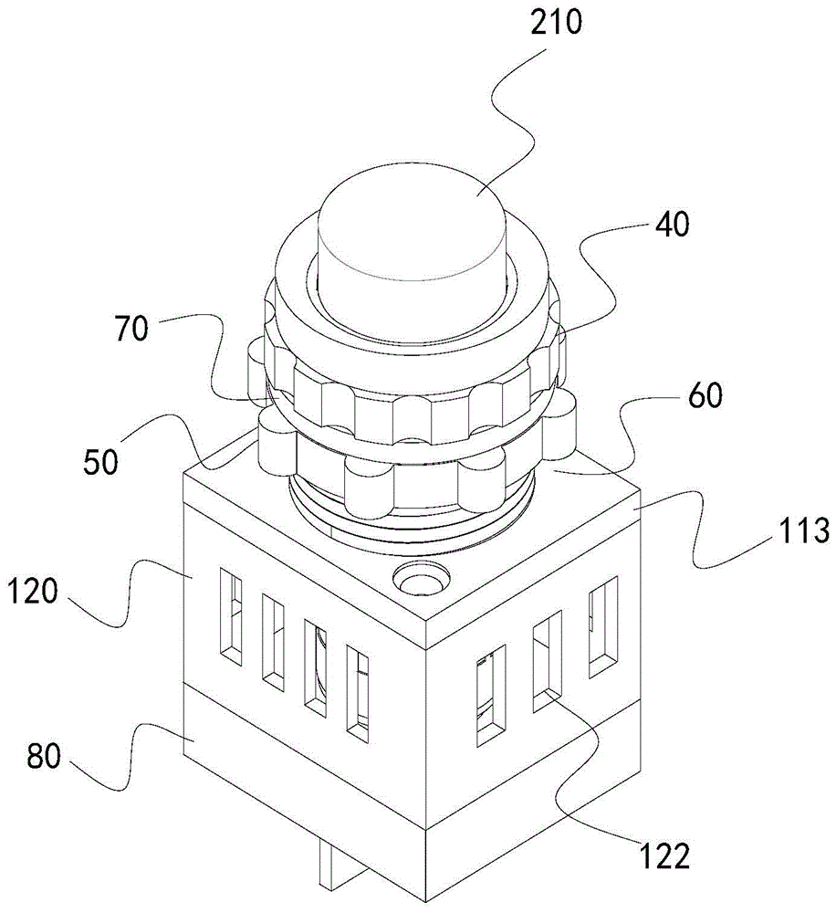
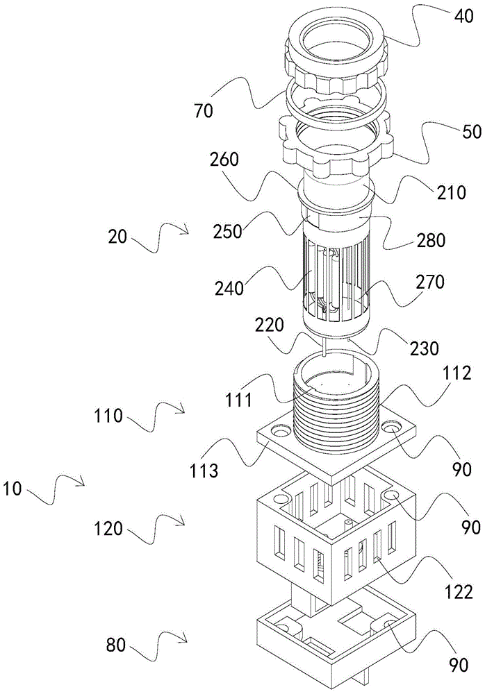
[0027] Such as Figure 1 to Figure 3 As shown, a substation indicator light includes a base 10 and a light-emitting assembly 20. The light-emitting assembly 20 includes a lamp base 210, a first pin 220, a second pin 230 connected to the lamp base 210 at one end, at least two resistors 240, and the resistor 240 One end is connected to the lamp holder 210, and the other end is connected to the first pin 220. The base 10 includes a first shell 110, a second shell 120 located below the first shell 110, a first pin tube 130 inside the second shell 120, The second pin tube 140, the first conductive sheet 310 and the second conductive sheet 320, the first shell 110 communicates with the second shell 120 and is detachably connected with the second shell 120, and the light-emitting component 20 is sleeved on the first shell 110 and the second shell 120. In the second ...


PUM


Abstract

The invention relates to a substation indicator lamp. The substation indicator lamp comprises a pedestal and a light emitting component, wherein the light emitting component comprises a lamp cap, a first pin with one end connected with the lamp cap and at least two resistors, wherein certain ends of the resistors are connected with the lamp cap, and the other ends are connected with the first pin; the pedestal comprises a first shell, a second shell on the lower side of the first shell, a first pin tube in the second shell, a second pin tube, a first conductive sheet and a second conductive sheet; the first shell is communicated with the second shell and is detachably connected with the second shell; the light emitting component sleeves in the first shell and the second shell; the end, away from the resistors, of the first pin penetrates through the first pin tube and is abutted against the first conductive sheet, and the end, away from the resistors, of the second pin penetrates through the second pin tube and is abutted against the second conductive sheet. The electrifiable plug-pull design is adopted by the light emitting component; the replacement and the maintenance are easy and convenient; professional maintenance skill is not required for maintenance; the pedestal is designed without circuit elements, and is not required to be replaced after mounting, so the maintenance cost is reduced.

Description

technical field [0001] The invention relates to the technical field of electric power supply, in particular to a substation indicator light. Background technique [0002] At present, substation indicator lights for live indication are widely used in substations. Since the indicator lights of the substation operate on the working site of the substation, affected by factors such as temperature, humidity, vibration, etc., the indicator lights of the substation have a high failure rate and often need maintenance. The replacement of substation indicator lights generally adopts the live replacement method, which requires professional maintenance personnel to operate, and the on-duty personnel do not have the ability to replace them, so the maintenance personnel must go to the site to replace them, resulting in untimely maintenance, which not only reduces work efficiency, but also increases traffic costs and costs. Labor cost; and after the existing substation indicator light is d...

Claims


Application Information

Patent Timeline
Patent Type & Authority Patents(China)
IPC IPC(8): F21S8/00F21V19/04F21V29/50
CPCF21S8/00F21V19/00F21V21/00F21V23/02F21V23/06
Inventor 刘威葳曾文斐陈远军周哲李信王杰
Owner GUANGZHOU POWER SUPPLY BUREAU GUANGDONG POWER GRID CO LTD
Features
  • R&D
  • Intellectual Property
  • Life Sciences
  • Materials
  • Tech Scout
  • Unparalleled Data Quality
  • Higher Quality Content
  • 60% Fewer Hallucinations
Learn More