Brightness enhancement film, preparation method therefor, and optical composite film

A technology of brightness enhancement film and optical film, applied in the field of optical film, can solve the problem of insufficient brightness gain of the brightness enhancement film

Inactive Publication Date: 2015-08-05
ZHANGJIAGANG KANGDE XIN OPTRONICS MATERIAL
View PDF3 Cites 3 Cited by
  • Summary
  • Abstract
  • Description
  • Claims
  • Application Information

AI Technical Summary

Problems solved by technology

[0006] The main purpose of the present invention is to provide a brightness enhancement film, its preparation method and opt

Method used


Image

  • Brightness enhancement film, preparation method therefor, and optical composite film

Examples


preparation example Construction

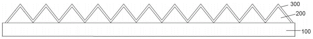
[0036] In addition, the present invention also provides a method for preparing a brightness enhancement film, which includes the following steps: forming a light concentrating layer 200 composed of a plurality of light concentrating structures on the upper surface of the substrate 100, the light concentrating structures having The upper surface of the 100 is in contact with the bottom surface, and the upper surface of the light-gathering layer 200 has a concave-convex structure; the refraction layer 300 is formed on the upper surface of the light-gathering layer 200, and the refraction layer 300 has the same surface as the light-gathering layer 200. A concave-convex structure that matches the concave-convex structure.

[0037] In the above preparation method provided by the present invention, a refraction layer 300 with a relatively high refractive index is attached on the upper surface of the light concentrating layer 200 . Since the light-gathering structure in the light-gat...

Embodiment 1

[0045] Substrate:

[0046] Using polyethylene terephthalate (PET) film as the substrate;

[0047] Production of light-concentrating layer:

[0048] A 9-inch self-made metal mother board is placed on a hot plate and heated to 60°C. The metal mother board is composed of linear arrangements of 90-degree isosceles triangular prisms with a nominal pitch interval of 50 microns. The UV-curable resin composition (refractive index: 1.6, see the table below for the composition) was applied to the master tool using a disposable pipette. Orient the PET film so that the orientation of the linear prisms is roughly perpendicular (90 ± 20°) to the high-gain axis of the film. The master tool, photocurable resin composition and PET film were then passed through a heated nip roll at 60° C., which applied sufficient pressure to completely fill the master tool with the resin while removing entrapped air. The filled master tool was then exposed twice to UV radiation from a "D-tube" at a line spe...

Embodiment 2

[0053] Substrate:

[0054] Using polyethylene terephthalate (PET) film as the substrate;

[0055] Production of light-concentrating layer:

[0056] A 9-inch self-made metal mother board is placed on a hot plate and heated to 60°C. The metal mother board is composed of linear arrangements of 90-degree isosceles triangular prisms with a nominal pitch interval of 50 microns. The UV-curable resin composition (refractive index: 1.52, see the table below for the composition) was applied to the master tool respectively using a disposable pipette. Orient the PET film so that the orientation of the linear prisms is roughly perpendicular (90 ± 20°) to the high-gain axis of the film. The master tool, photocurable resin composition and PET film were then passed through a heated nip roll at 60° C., which applied sufficient pressure to completely fill the master tool with the resin while removing entrapped air. The filled master tool was then exposed twice to UV radiation from a "D-tube"...


PUM

PropertyMeasurementUnit
Thicknessaaaaaaaaaa
Thicknessaaaaaaaaaa

Abstract

The invention provides a brightness enhancement film, a preparation method therefor, and an optical composite film. The brightness enhancement film sequentially comprises a base material, a condensation layer and a refraction layer from the bottom to the top, wherein the condensation layer consists of a plurality of condensation structures. The condensation structures are respectively provided with a bottom surface which contacts with the upper surface of the base material. The refractive index of the refraction layer is greater than the refractive index of the condensation layer, and the upper surface of the refraction layer is provided with a concave-convex structure which is matched with a concave-convex structure on the upper surface of the condensation layer. In the above brightness enhancement film, the upper surface of the condensation layer is provided with a refraction layer with relatively high refractive index in an attaching manner. The upper surface of the refraction layer is enabled to be provided with the concave-convex structure matched with the concave-convex structure on the upper surface of the condensation layer, thereby equivalently enabling the surface of the brightness enhancement film to maintaining the geometrical shapes of the condensation structures. The refraction layer with the high refractive index can remarkably improve the condensation degree of light on the brightness enhancement film, thereby improving the brightness gain of the brightness enhancement film. Meanwhile, the geometrical shapes of the condensation structures are maintained, thereby preventing the arrangement of the refraction layer from causing the change of the geometrical optical effect.

Description

technical field [0001] The invention relates to the field of optical films, in particular to a brightness enhancing film, a preparation method thereof and an optical composite film. Background technique [0002] Brightness enhancing films are used in many electronic products to increase the brightness of backlit flat panel displays such as liquid crystal displays (LCDs), including electroluminescent panels, laptop computers, word processors, desktop monitors, televisions, The ones for video cameras, and the monitors for cars and airplanes. Improvements in brightness allow illuminated displays to use less energy and enable electronics to operate more efficiently, resulting in less energy consumption, lower thermal load on components, and longer product life. [0003] Brightness enhancement film is a film with a series of regular parallel prisms on the surface of the film, which converts side light into front light and collects reflected light through prisms to improve bright...

Claims


Application Information

Patent Timeline
IPC IPC(8): G02B5/04G02B3/00
CPCG02B5/045G02B3/0056
Inventor 许小健陈明源丁清华
Owner ZHANGJIAGANG KANGDE XIN OPTRONICS MATERIAL
Why Eureka
Try Eureka