
Photovoltaic charging control system and control method

A charging control, photovoltaic voltage technology, applied in the direction of collectors, electric vehicles, electrical components, etc., to achieve real-time sampling, simple structure, low cost

Active Publication Date: 2015-08-05
湖南终南山科技发展有限公司
View PDF5 Cites 6 Cited by
  • Summary
  • Abstract
  • Description
  • Claims
  • Application Information

AI Technical Summary

Problems solved by technology

It solves the sampling problem of the current common positive charging circuit when the switch tube is turned off and the control problem when the circuit is not shared.

Method used


Image

  • Photovoltaic charging control system and control method
  • Photovoltaic charging control system and control method

Examples


Embodiment Construction

[0034] The following will clearly and completely describe the technical solutions in the embodiments of the present invention with reference to the accompanying drawings in the embodiments of the present invention. Obviously, the described embodiments are only some of the embodiments of the present invention, not all of them. Based on the embodiments of the present invention, all other embodiments obtained by persons of ordinary skill in the art without making creative efforts belong to the protection scope of the present invention.

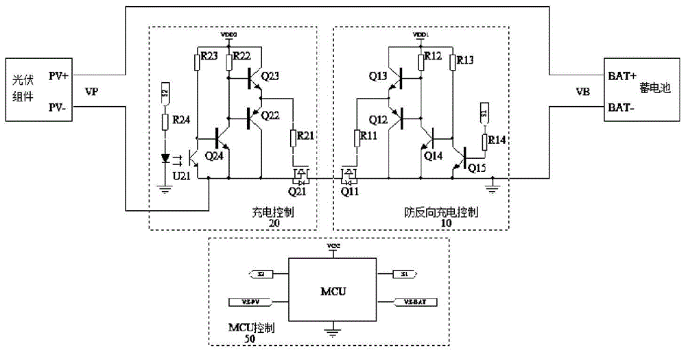
[0035] In order to overcome the defects and deficiencies of the prior art, the present invention provides a photovoltaic charging control system, which can sample photovoltaic voltage in real time, has a simple structure, low cost, high-speed switching, and is stable and reliable. The invention also provides a control method based on the photovoltaic charging control system. The present invention solves the sampling problem when the switch tube i...


PUM


Abstract

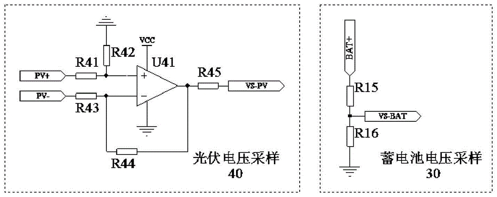
The invention provides a photovoltaic charging control system. The system comprises a control module and a voltage sampling module, one end of the control module is connected with a photovoltaic assembly, and the other end of the control module is connected with a storage battery; the control module comprises a charging control module, an anti-reverse charging control module and an MCU control module; and the voltage sampling module comprises a photovoltaic voltage sampling module and a storage battery voltage sampling module. The control system can samples a photovoltaic voltage in real time, and has the advantages of simple structure, low cost, high-speed switching, high stability and high reliability. The invention further provides a control method based on the photovoltaic charging control system, and solves the sampling problem of an existing common anode charging circuit in a switch tube turn-off period and the control problem when a circuit does not share the ground.

Description

technical field [0001] The invention relates to the field of photoelectric technology, in particular to a photovoltaic charging control system and control method. Background technique [0002] At present, there are many ways to apply the photovoltaic charging circuit, and one of the typical ways is that the photovoltaic panel directly charges the battery through an electronic switch. This charging method is divided into two types: common positive connection and common negative connection. The common positive connection method can use N-channel MOS transistors with low on-resistance as the switching tubes on the low side and does not require an isolated driving power supply. It has low charging loss, low heat generation, fewer components, small circuit size, and low cost. It is widely used in small and medium power photovoltaic power generation systems. For example, this kind of charging circuit is widely used in off-grid photovoltaic street lighting systems. However, sinc...

Claims


Application Information

Patent Timeline
IPC IPC(8): H02J7/00
Inventor 袁金钢
Owner 湖南终南山科技发展有限公司
Learn More