A kind of service brake system and vehicle

A technology of driving brakes and brakes, which is applied in the field of vehicles, and can solve problems such as poor thermal degradation resistance and reliability, and large differences in braking torque between the left and right wheels of the rear axle.

Active Publication Date: 2018-06-19
BEIQI FOTON MOTOR CO LTD
View PDF6 Cites 0 Cited by
  • Summary
  • Abstract
  • Description
  • Claims
  • Application Information

AI Technical Summary

Problems solved by technology

[0005] The invention provides a service braking system, which is used to solve the problems of large difference in braking torque of the left and right wheels of the rear axle, poor thermal fading resistance and poor reliability when the vehicle equipped with the existing service braking system brakes

Method used


Image

  • A kind of service brake system and vehicle
  • A kind of service brake system and vehicle
  • A kind of service brake system and vehicle

Examples


Embodiment Construction

[0020] The specific implementation manners of the service brake system and the vehicle provided by the embodiments of the present invention will be described below with reference to the accompanying drawings.

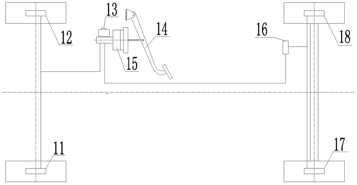
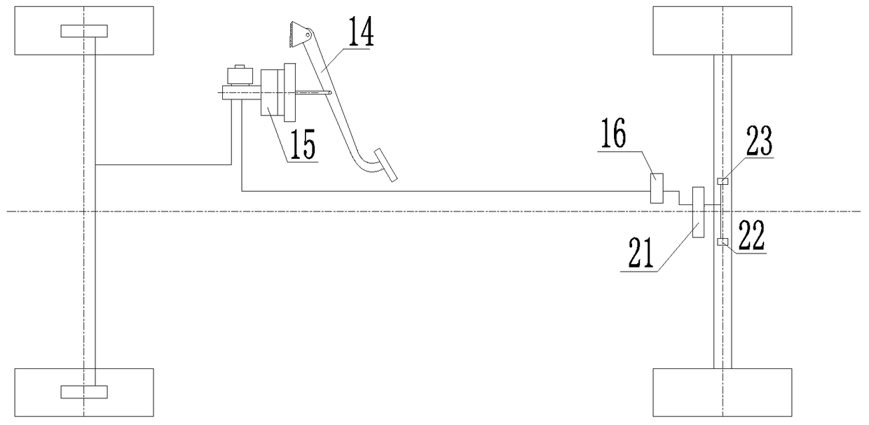
[0021] The embodiment of the present invention provides a service braking system, which includes: a brake pedal assembly 14, a front brake circuit and a rear brake circuit, and the brake pedal assembly 14 is connected to the front brake circuit and the rear brake circuit respectively. The circuit is connected, wherein: the brake pedal assembly 14, the structure of the front brake circuit can be referred to as figure 1 The structures of the brake pedal assembly 14 and the front brake circuit in the shown existing service brake system. Different from the prior art, in the service brake system provided by the present invention, the rear brake circuit includes: the second chamber of the master cylinder assembly 15, the central brake assembly 21, the left differential lock a...


PUM


Abstract

A running brake system and a vehicle. A rear brake loop in the running brake system comprises a left differential lock assembly (22) and a right differential lock assembly (23). When a pedal of a brake pedal assembly (14) is treaded, the rear brake loop is used for braking an input shaft of a rear axle differential, and the left differential lock assembly (22) and the right differential lock assembly (23) make the rear axle differential lose the differential effect under the hydraulic effect. When the running brake system needs to carry out braking, the rear axle can be braked as a whole by means of the rear axle differential, therefore the phenomenon is avoided that when an automobile is braked, large difference exists in brake torque of a left wheel and brake torque of a right wheel of a rear axle due to influence of poor component consistency, and accordingly, the brake stability is improved, thereby solving the problems that an existing running brake system is poor in heat-fading resistance and reliability.

Description

technical field [0001] The invention relates to the field of vehicles, in particular to a service braking system and a vehicle. Background technique [0002] Traditional service brake systems such as figure 1 As shown, it includes left front brake assembly 11, right front brake assembly 12, oil storage cup assembly 13, brake pedal assembly 14, master cylinder assembly 15, pressure regulating valve assembly 16, left rear brake assembly 17 and Right rear brake assembly 18. [0003] When braking, depress the pedal in the brake pedal assembly 14, so that the brake fluid stored in the oil storage cup assembly 13 passes through the master cylinder assembly 15 to build up pressure to form two circuits, and the master cylinder assembly 15 There are two oil chambers. For the convenience of explanation, the first chamber and the second chamber are respectively used below to distinguish the two chambers of the master pump assembly. Among them, the first chamber (also known as the fro...

Claims


Application Information

Patent Timeline
Patent Type & Authority Patents(China)
IPC IPC(8): B60T11/24
CPCB60T13/18F16H48/20F16H48/27
Inventor 颜中国梁勋乾栾义超刘灵虎刘志勇
Owner BEIQI FOTON MOTOR CO LTD
Why Eureka
Try Eureka