Electroplating drum unit

A technology for electroplating drums and drums, applied in the electrolysis process, electrolysis components and other directions, can solve problems such as labor costs, and achieve the effect of improving the level of automation, reducing labor costs, and saving labor costs.

Active Publication Date: 2015-08-12
中山市瀚成电镀设备有限公司
View PDF8 Cites 1 Cited by
  • Summary
  • Abstract
  • Description
  • Claims
  • Application Information

AI Technical Summary

Problems solved by technology

However, the existing electroplating barrels generally have a bung mouth on its circumferential wall, and the bung lid is used to close the bung mouth, but in the process of loading or unloading, the switch of the bung must be manually intervened. Consume the corresponding labor cost

Method used


Image

  • Electroplating drum unit
  • Electroplating drum unit
  • Electroplating drum unit

Examples


Embodiment Construction

[0024] Below, in conjunction with accompanying drawing and specific embodiment, the present invention is described further:

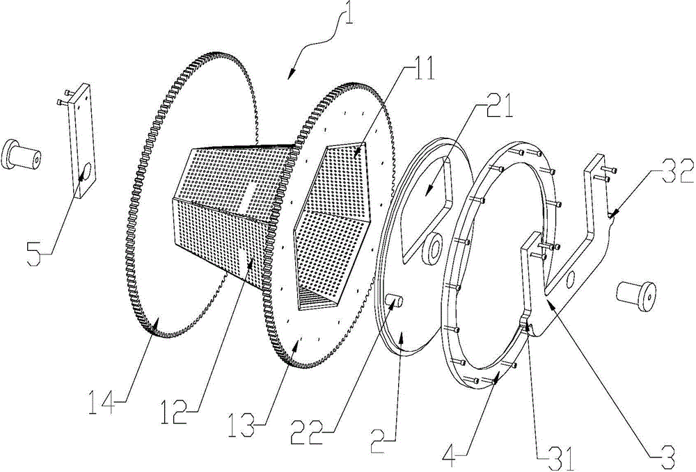
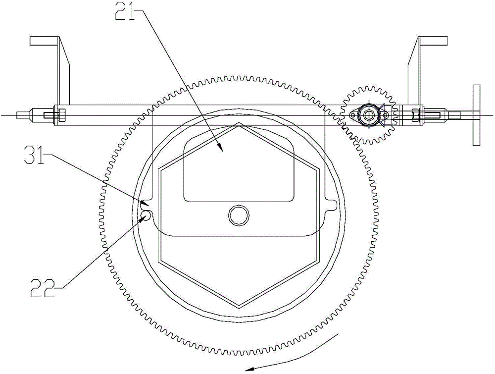
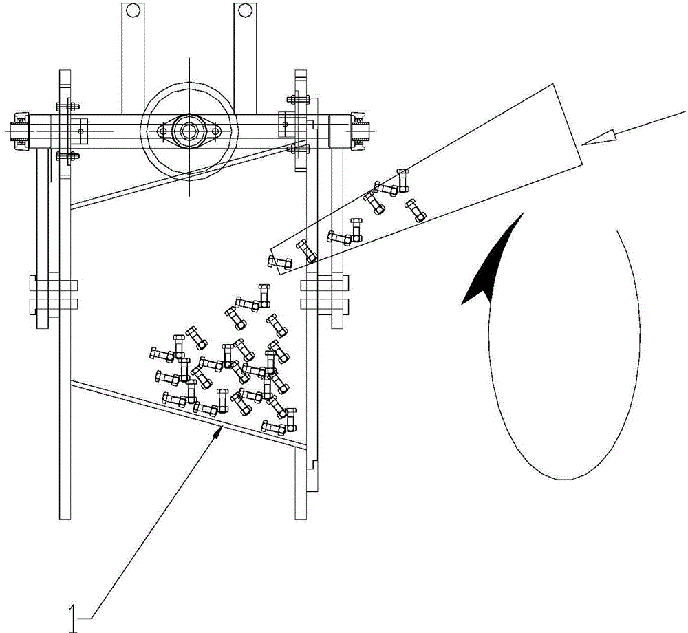
[0025] Such as Figure 1-6 As shown, the electroplating drum device of the present invention includes a hollow drum 1, a movable cover 2 that is in frictional contact with the front end of the drum 1 and can rotate with the drum 1 under the action of friction, and a stopper The front end of the drum 1 is provided with an over-center front opening 11; the movable cover 2 is provided with an inlet and outlet 21 and a positioning part 22; Stopper 32; the positioning part 22 can move between the first stopper 31 and the second stopper 32 with the rotation of the movable cover 2; the positioning part 22 moves to abut against the first stopper 31 When the material inlet and outlet 21 is facing the upper end of the front opening 11 of the drum 1;

[0026] In use, when the drum 1 rotates clockwise under the action of external force, the movable cover 2 rotate...


PUM


Abstract

The invention discloses an electroplating drum unit comprising a drum which is hollow, a moving cover, and a limiting part. The moving cover in friction contact with the front end of the drum can rotate with the drum under the friction action. The front end of the drum is provided with a front opening passing the center. The moving cover is provided with an access opening and a positioning part. The limiting part comprises a first stop part and a second stop part. The positioning part can move between the first stop part and the second stop part along with rotation of the moving cover. When the positioning part moves to abut to the first stop part, the access opening faces the upper end of the front opening of the drum; when the positioning part moves to abut to the second stop part, the access opening faces the lower end of the front opening of the drum. The electroplating drum unit has the advantages that the avoidance of manual cover opening and closing saves labor cost; automation level is higher; the drum with reasonably set structure allows automatic discharging and helps further reduce the labor cost.

Description

technical field [0001] The invention relates to an electroplating drum device. Background technique [0002] With the development of the national economy and the progress of the manufacturing industry, enterprises in the surface treatment industry have further increased their requirements for high automation of equipment. At present, the electroplating process has a long process efficiency, which is roughly divided into pretreatment (degreasing), electroplating (or multi-coating), post-treatment (passivation and sealing, etc.) and dehydration and drying. In order to change the process function in each process, it is necessary to load and unload multiple times. In the market, the electroplating drum is generally used to load the material, and during the working process, the drum is driven by a rotating drive device to rotate. However, the existing electroplating barrels generally have a bung mouth on its circumferential wall, and the bung lid is used to close the bung mouth,...

Claims


Application Information

Patent Timeline
Patent Type & Authority Applications(China)
IPC IPC(8): C25D17/20
Inventor 梅苏鸿
Owner 中山市瀚成电镀设备有限公司
Why Eureka
Try Eureka