Diesel particulate filter (DPF) carbon accumulation estimation method

A particle trap and carbon accumulation technology, which is applied in the direction of machines/engines, mechanical equipment, engine components, etc., can solve problems such as unreliability, low calculation accuracy, difficulty in implementation, and poor estimation accuracy, so as to improve accuracy , improve calculation accuracy, and simplify the judgment process

Inactive Publication Date: 2015-08-12
SOUTHWEST JIAOTONG UNIV
View PDF7 Cites 26 Cited by
  • Summary
  • Abstract
  • Description
  • Claims
  • Application Information

AI Technical Summary

Problems solved by technology

At present, there are many methods for judging the timing of regeneration, such as threshold exhaust back pressure method, fuel consumption method, exhaust back pressure, speed and load combination method, but these methods have certain shortcomings, such as unreliability and complicated calculation etc., which directly affect the accuracy of judging the timing of regeneration
[0005] Chinese Patent Announcement No. CN 103016104 A discloses a method and device for calculating carbon accumulation, but the calculation process uses many correction coefficients with unclear physical meanings, and it is difficult to obtain the coefficients, which also leads to low calculation accuracy, and its The calculation process is too complicated, and the practicability is not high; Chinese Patent Publication No. CN 103511043 A pro...

Method used


Image

  • Diesel particulate filter (DPF) carbon accumulation estimation method
  • Diesel particulate filter (DPF) carbon accumulation estimation method
  • Diesel particulate filter (DPF) carbon accumulation estimation method

Examples


Embodiment Construction

[0052] The present invention will be further described below in conjunction with the accompanying drawings. The following descriptions are only preferred embodiments of the present invention, and therefore do not limit the protection scope of the present invention.

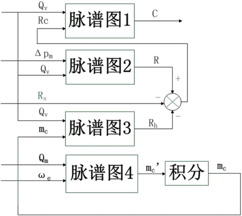
[0053] The present invention proposes a new method for calculating the carbon accumulation of diesel particulate traps, which avoids the use of many correction coefficients with unclear physical meanings, improves the calculation accuracy of carbon accumulation, and simplifies the judgment process of carbon accumulation. Significantly improved the accuracy of judging the timing of DPF regeneration.

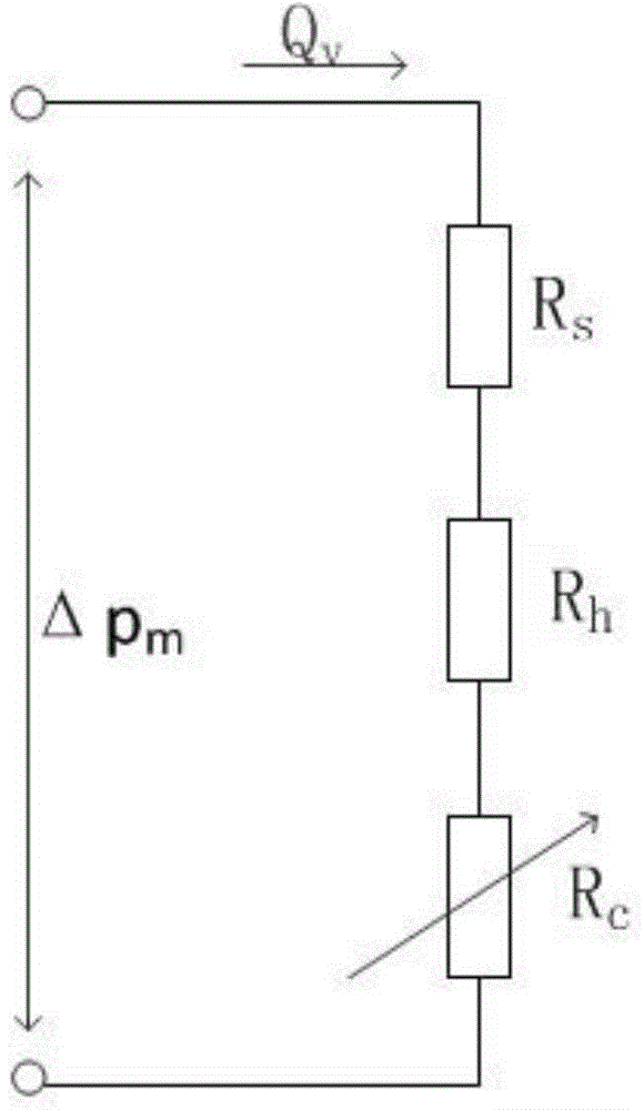
[0054] The total pressure difference before and after the DPF is measured by the pressure sensor;

[0055] According to the total pressure difference before and after the DPF and the exhaust gas volume flow rate, the total flow resistance of the DPF is obtained;

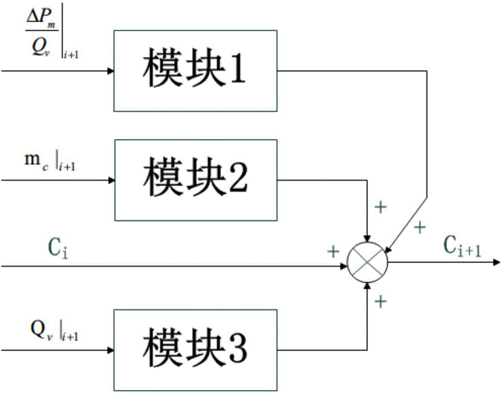
[0056] According to the mass of ash and the volume f...


PUM


Abstract

The invention discloses a diesel particulate filter (DPF) carbon accumulation estimation method. The difference between total pressure before a DPF and total pressure after the DPF is detected by a pressure difference sensor, the total flow resistance of the DPF is obtained according to the difference between the total pressure before the DPF and the total pressure after the DPF and exhaust gas volume flow, the flow resistance generated by the residual carbon of the DPF is obtained according to ash content mass and the exhaust gas volume flow, white carrier flow resistance and the flow resistance generated by the residual carbon subtracted from the total flow resistance gives flow resistance generated by accumulated carbon, and according to the flow resistance generated by the accumulated carbon and the exhaust gas volume flow, carbon accumulation can be obtained; the ash content mass is obtained by integrating exhaust gas mass flow and the rotational speed of an engine. The carbon accumulation increment estimation method put forward by the invention can work out the increment of carbon accumulation on the basis of current total flow resistance, current ash content mass and current exhaust gas volume flow, and then obtains current carbon accumulation. The precision of the DPF carbon accumulation estimation obtained by the method disclosed by the invention is higher, moreover, parameters, the physical meaning of which is unclear, in conventional estimation methods are prevented from being used, the estimation process is quicker and more accurate, and thereby the accuracy of DPF regeneration opportunity judgment is greatly increased.

Description

technical field [0001] The invention relates to the field of after-treatment of automobile exhaust gas, in particular to a new method for estimating the carbon accumulation of a diesel particulate filter (DPF). Background technique [0002] The combustion thermal efficiency, power and economy of diesel engines are better than those of gasoline engines, so diesel engines are more and more widely used. However, due to the poorer emission characteristics of diesel engines than gasoline engines, they are more harmful to the environment. Its pollutants are mainly particulate emissions, which have a serious impact on human health. With the increasingly stringent emission regulations, exhaust after-treatment devices have become a standard configuration for diesel vehicles to solve the problem of carbon particulate emissions. Currently, Diesel Particulate Filter (DPF) is recognized as the most effective post-treatment method for diesel particulates. [0003] DPF is a filter instal...

Claims


Application Information

Patent Timeline
IPC IPC(8): F01N11/00
CPCY02T10/40
Inventor 胡广地余胜郭瑞华张轲杜艳婷
Owner SOUTHWEST JIAOTONG UNIV
Why Eureka
Try Eureka