LED lamp heat dissipation structure

A heat dissipation structure, LED lamp technology, applied in lighting and heating equipment, cooling/heating devices for lighting devices, lighting devices, etc. Service life and the effect of improving heat dissipation efficiency

Active Publication Date: 2015-08-12
LEEDARSON IOT TECH INC
View PDF8 Cites 5 Cited by
  • Summary
  • Abstract
  • Description
  • Claims
  • Application Information

AI Technical Summary

Problems solved by technology

When the LED light source is working, it will emit a lot of heat. The greater the power, the more heat will be emitted. If it is made of plastic materials, its thermal conductivity is small and heat transfer is slow, which affects the speed and efficiency of heat transmission. The temperature of the heat dissipation shell itself rises, which also directly affects the normal operation of the LED, causing the LED temperature to be too high, which is very easy to fail or affect the safety of the lamp.

Method used


Image

  • LED lamp heat dissipation structure
  • LED lamp heat dissipation structure
  • LED lamp heat dissipation structure

Examples


Embodiment Construction

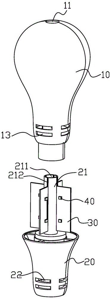
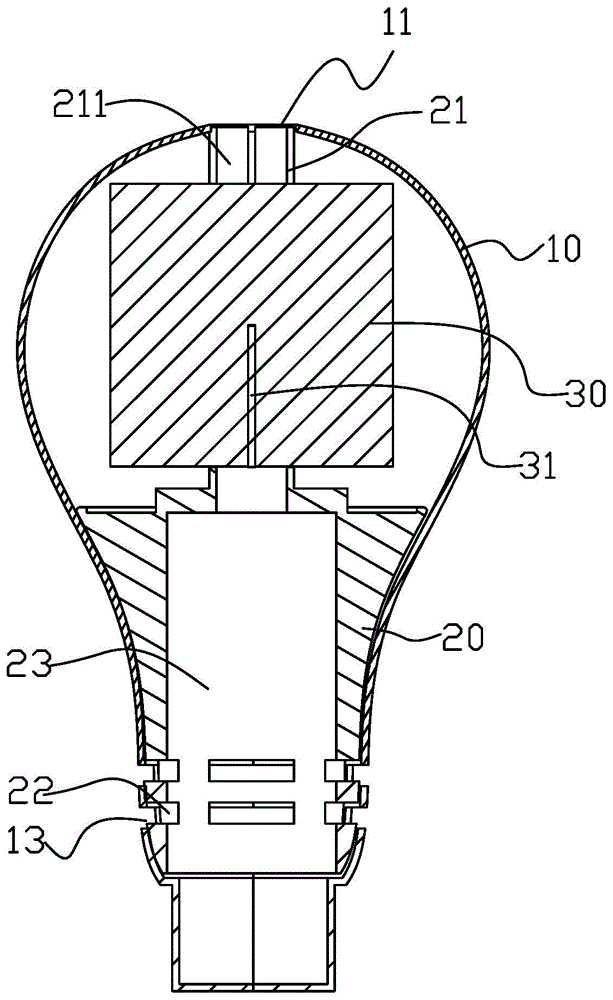
[0014] figure 1 It is a three-dimensional exploded view of the heat dissipation structure of the LED lamp according to the first embodiment of the present invention. The heat dissipation structure of the LED lamp includes a bulb shell 10, a lamp holder shell 20, and a substrate 30 thermally connected to the LED light source 40. The bulb shell 10 is covered by the A cavity is formed on the lamp housing 20 and the top of the lamp housing 20 to accommodate the substrate 30 .

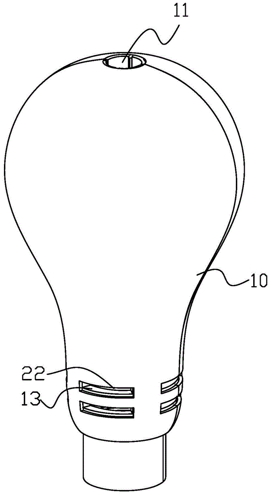
[0015] Please refer to figure 1 and figure 2 , the bulb shell 10 is provided with first air holes 11 , and these first air holes 11 are arranged on the top of the light bulb shell 10 . The bulb shell 10 is a hemispherical bulb shell structure, and the bulb shell 10 is formed by buckling two half shells.

[0016] Please refer to Figure 1 to Figure 3 , the top of the lamp housing 20 is provided with a ventilation column 21 , and the ventilation column 21 is integrally formed with the lamp housing 20 . ...


PUM


Abstract

The invention provides an LED lamp heat dissipation structure. The LED lamp heat dissipation structure comprises a bulb shell, a lamp cap shell and a substrate thermally connected with LED light sources. The bulb shell covers the lamp cap shell, a cavity is formed between the bulb shell and the top of the lamp cap shell so as to contain the substrate, a first vent hole is formed in the bulb shell, second vent holes are formed in the lamp cap shell, a ventilating column is arranged at the top of the lamp cap shell and located in the cavity, the middle of the ventilating column is provided with a vertically-through airflow channel, the airflow channel of the ventilating column is communicated with the first vent hole and the second vent holes, part of the substrate is connected to the ventilating column, and at least part of the substrate stretches into the airflow channel of the ventilating column. The LED lamp heat dissipation structure has the advantage of being high in heat dissipation efficiency.

Description

technical field [0001] The invention relates to the field of LED lighting, in particular to a heat dissipation structure of an LED lamp. Background technique [0002] Existing LED lamps are more and more widely used. Considering the high-temperature overheating phenomenon generated when the light-emitting diodes are working, it is necessary to combine the heat sink to achieve the purpose of auxiliary heat dissipation. When the LED light source is working, it will emit a lot of heat. The higher the power, the more heat it emits. If it is made of plastic materials, its thermal conductivity is small and heat transfer is slow, which affects the speed and efficiency of heat transmission. The temperature rise of the heat dissipation housing itself also directly affects the normal operation of the LED, resulting in excessive temperature of the LED, which is very likely to fail or affect the safety of the lamp. Contents of the invention [0003] In view of this, it is necessary t...

Claims


Application Information

Patent Timeline
IPC IPC(8): F21S2/00F21V29/83F21V29/503F21Y101/02F21Y111/00
CPCF21K9/232F21Y2107/00F21Y2115/10
Inventor 马志超郭伟杰
Owner LEEDARSON IOT TECH INC
Why Eureka
Try Eureka