Heat exchanger

A heat exchanger and fin technology, applied in the field of heat exchangers, can solve the problems of increasing the defrosting time of the heat exchanger, narrowing the space of tubes and fins, reducing heat exchange efficiency, etc. The effect of air volume and long flow distance

Inactive Publication Date: 2015-08-12
LG ELECTRONICS INC
View PDF7 Cites 2 Cited by
  • Summary
  • Abstract
  • Description
  • Claims
  • Application Information

AI Technical Summary

Problems solved by technology

[0005] With such a conventional heat exchanger, when the above-mentioned heat exchanger is used as an evaporator at a low temperature outside, frost may occur on the surface of the fin due to freezing
[0006] In particular, based on the overall structure of the heat exchanger, there is a problem that more frost is formed on the front end side of the heat exchanger where the flowing air meets first.
This is because the temperature difference between the air at the front end side and the refrigerant is greater than the temperature difference between the air at the rear end side of the heat exchanger and the refrigerant, and thus the degree of condensation is large.
[0007] Also, in the case where the fins are formed with louvers, due to the narrowed lamination distance, a phenomenon occurs that the space between the tubes provided on the front end side of the heat exchanger and the fins is clogged with frost.
[0008] In this way, when a lot of frosting occurs, since the flow path of air can be blocked, there is a problem that the heat exchange efficiency is lowered and the time for defrosting of the heat exchanger is increased.

Method used


Image

  • Heat exchanger
  • Heat exchanger
  • Heat exchanger

Examples


Embodiment Construction

[0043] Hereinafter, specific embodiments of the present invention will be described with reference to the drawings. However, the idea of ​​the present invention is not limited to the suggested embodiments, and those skilled in the art who understand the idea of ​​the present invention can easily propose other embodiments within the scope of the same idea.

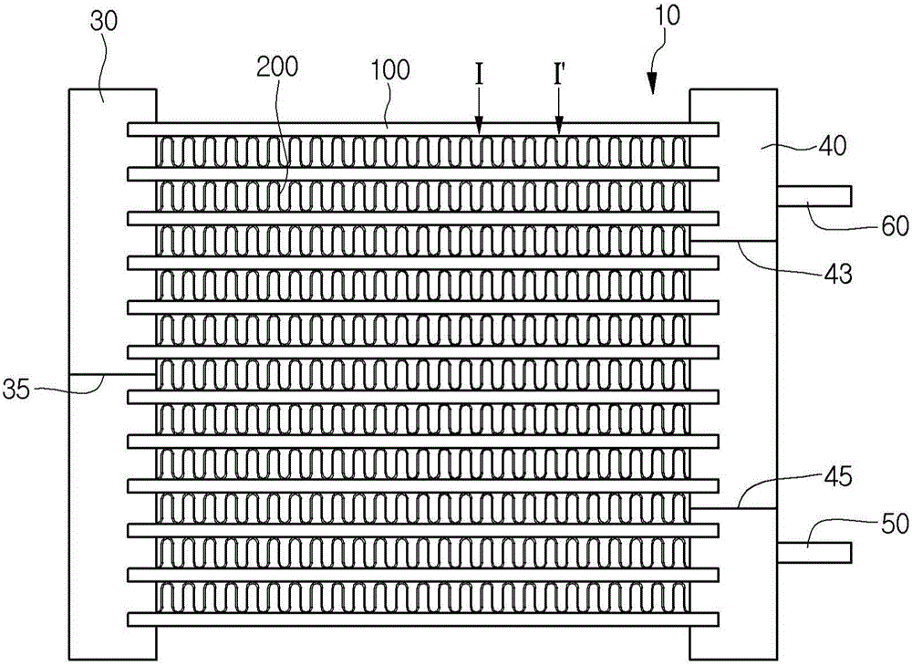
[0044] figure 1 It is a front view showing the structure of the heat exchanger of the first embodiment of the present invention.

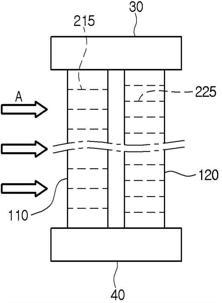
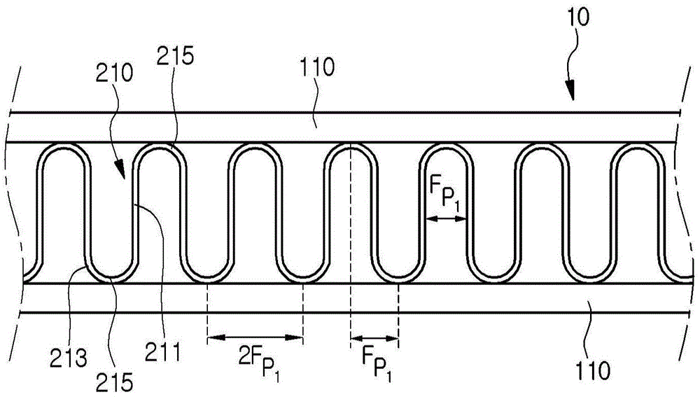
[0045] refer to figure 1 , The heat exchanger 10 of the first embodiment of the present invention includes: a plurality of refrigerant tubes (hereinafter, "tubes") 100 capable of causing refrigerant to flow; a plurality of fins 200 stacked on the above-mentioned refrigerant tubes 100; and two Two heads 30, 40 are connected to the two ends of the above-mentioned refrigerant pipe 100.

[0046] The plurality of refrigerant tubes 100 have a predetermined length, are arranged long in parallel to e...


PUM


Abstract

Provided is a heat exchanger. The heat exchanger includes a plurality of refrigerant tubes through which a refrigerant flows, the plurality of refrigerant tube being disposed to be spaced apart from each other in one direction and a plurality of fins disposed between the plurality of refrigerant tubes. A distance between the fins disposed on a front end-side of the plurality of refrigerant tubes is greater than that between the fins disposed on a rear end-side of the plurality of refrigerant tubes.

Description

technical field [0001] The present invention relates to heat exchangers. Background technique [0002] The heat exchanger is used as a structural element constituting the refrigerant cycle to make the refrigerant flow. And, the heat exchanger performs a function of cooling or heating the air by exchanging heat with the air. The heat exchanger described above can be used in refrigerating devices such as air conditioners and refrigerators, and can function as a condenser or an evaporator by condensing or evaporating a refrigerant using the heat exchanger. [0003] According to the shape, this kind of heat exchanger is roughly divided into finned tube type and micro channel type. The above-mentioned fin-tube heat exchanger includes a plurality of fins and circular or similar-shaped tubes passing through the plurality of fins, and the above-mentioned micro-channel heat exchanger includes a plurality of tubes (flat tubes) through which the refrigerant flows. tube) and the fins...

Claims


Application Information

Patent Timeline
Patent Type & Authority Applications(China)
IPC IPC(8): F25B39/00
CPCF28F2215/04F28F1/128F28F19/006F25B39/00F25B2500/01F25B2500/09F28D1/05375F28D1/05383
Inventor 朴泰均郑承模金世显
Owner LG ELECTRONICS INC
Why Eureka
Try Eureka