Center hole detection device

A detection device and tip hole technology, applied in the direction of measuring device, mechanical measuring device, mechanical device, etc., can solve the problems of low efficiency, large measurement error, large measurement cost, etc., and achieve the effect of high efficiency

Inactive Publication Date: 2015-08-12
SUZHOU VOCATIONAL UNIV
View PDF4 Cites 2 Cited by
  • Summary
  • Abstract
  • Description
  • Claims
  • Application Information

AI Technical Summary

Problems solved by technology

[0003] Its shortcomings are: low efficiency, large measurement error, three-coordinate measurement, high measurement cost, and inconvenient on-site measurement

Method used


Image

  • Center hole detection device
  • Center hole detection device
  • Center hole detection device

Examples


Embodiment Construction

[0015] The preferred embodiments of the present invention will be described in detail below in conjunction with the accompanying drawings, so that the advantages and features of the present invention can be more easily understood by those skilled in the art, so as to define the protection scope of the present invention more clearly.

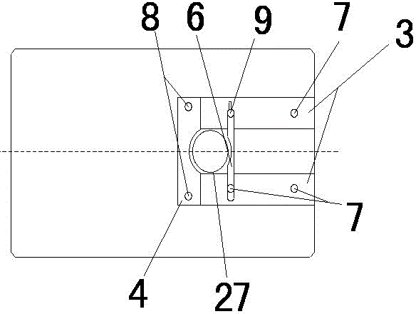
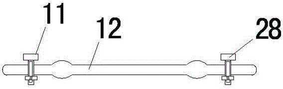
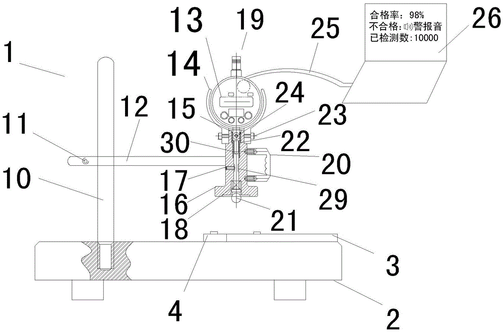
[0016] like figure 1 The embodiment of the present invention shown in -3, a center hole detection device, includes: a fixed frame 1, a test device 19 and a calibration block 27; the fixed frame 1 includes a column 10, a base 2 and a clamping frame 12, the The column 10 is vertically fixed on the upper surface of the base 2; the two ends of the clamping frame 12 are respectively provided with two through-hole grooves, and the two through-hole grooves are respectively provided with a screw one 11 and a screw two 28. 10 passes through the through-hole groove at one end and is fixed with the clamping frame 12 by screw one 11, and the other end throug...


PUM


Abstract

The invention discloses a center hole detection device comprising a fixing rack, a test device, and a calibration block. The fixing rack comprises a vertical column, a pedestal, and a clamping rack. The vertical column is vertically fixedly disposed on the upper surface of the pedestal, and the upper surface of the pedestal is provided with a positioning block, a guiding block, and a fixing block. The clamping rack is fixedly disposed on the vertical column by a screw 1. The test device is disposed on the clamping rack, and comprises a substrate and a ball rod. The substrate is provided with a main body, the side surface of which is provided with a handle. The upper end of the main body is provided with a supporting rack, which is provided with a dial indicator, which is connected with a computer by a data line. The ball rod is disposed on the center of the main body, and the ball end faces downwards, and the ball end is provided with a spring. The ball rod is provided with an annular-shaped groove, and a screw 3 in the annular-shaped groove can be used to prevent the ball rod from sliding down from the main body. The calibration block can be used for the calibration of the test device. The test device is disposed in the center hole, and the computer can be used to give the results. The center hole detection device can be used to determine whether the center hole is qualified quickly, accurately, and conveniently.

Description

technical field [0001] The invention relates to a tip hole detection device. Background technique [0002] In the prior art, vernier calipers, depth gauges, etc. are used for traditional measurement. [0003] Its shortcomings are: low efficiency, large measurement error, three-coordinate measurement, high measurement cost, and inconvenient on-site measurement. Contents of the invention [0004] The main technical problem to be solved by the present invention is to provide a top hole detection device, which can measure quickly and conveniently, can self-judgment qualified products and unqualified products, can give prompts to unqualified products, and has a statistical function. [0005] In order to solve the above technical problems, a technical solution adopted by the present invention is to provide a center hole detection device, including: a fixed frame, a test device and a calibration block; the fixed frame includes a column, a base and a clamping frame, and the colum...

Claims


Application Information

Patent Timeline
Patent Type & Authority Applications(China)
IPC IPC(8): G01B5/00
Inventor 王领赵竹新庞恭贺张楠祁彤彤刘旭
Owner SUZHOU VOCATIONAL UNIV
Why Eureka
Try Eureka