Check patentability & draft patents in minutes with Patsnap Eureka AI!

1-3 micrometer collimated light source radiation illumination measuring instrument

A technology of irradiance and collimated light sources, which is applied in the field of infrared light source irradiance measurement, can solve the problems of narrow measurement range and high uncertainty of infrared irradiance measurement, and achieve the effect of high-precision testing

Inactive Publication Date: 2015-08-12
HARBIN INST OF TECH
View PDF1 Cites 4 Cited by
  • Summary
  • Abstract
  • Description
  • Claims
  • Application Information

AI Technical Summary

Benefits of technology

This patented device measures brightness accurately over an entire visible spectrum from 3-5 micrometers (µm) upwards at wavelengths ranging between 5 nm - 70 nanometers). It has several technical benefits that make it useful for various applications such as optical communication or medical imaging.

Problems solved by technology

This patented technical solution describes how different types of laser devices (infrared lights) may generate electromagnetic waves with specific properties depending on their location within space. These techniques help identify potential issues related to improving the efficiency and effectiveness of these weapons systems. However, current methods require long exposure times before measuring the emitted radiances accurately enough.

Method used


Image

  • 1-3 micrometer collimated light source radiation illumination measuring instrument
  • 1-3 micrometer collimated light source radiation illumination measuring instrument
  • 1-3 micrometer collimated light source radiation illumination measuring instrument

Examples


specific Embodiment approach 1

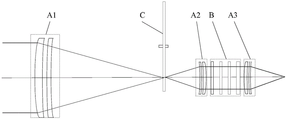
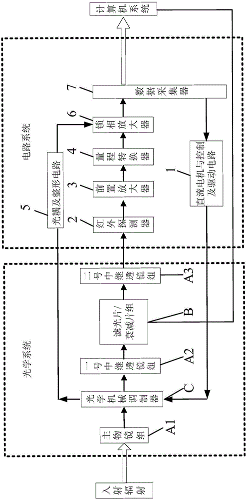
[0027] Specific implementation mode one: refer to figure 1 with figure 2 Specifically explain this embodiment, a 1-3 μm collimated light source radiation illuminance measuring instrument described in this embodiment, it includes: an optical system, a circuit system and a computer system;

[0028] The optical system includes a main objective lens group A1, an optical mechanical modulator C, a No. 1 relay lens group A2, an optical filter / attenuation sheet group B, and a No. 2 relay lens group A3;

[0029] The computer system includes a computer;

[0030] The circuit system includes a DC motor and a control and drive circuit 1, an infrared detector 2, a preamplifier 3, a lock-in amplifier 6 and a data collector 7;

[0031] The circuit system also includes a range converter 4 and an optocoupler and shaping circuit 5;

[0032] The main objective lens group A1 focuses the received collimated beam to the optical mechanical modulator C, and the optical mechanical modulator C trans...

specific Embodiment approach 2

[0053] Embodiment 2: This embodiment is a further description of the 1-3 μm collimated light source irradiance measuring instrument described in Embodiment 1. In this embodiment, the optical mechanical modulator C is a gold-plated reflective film modulator.

[0054] The optical mechanical modulator C not only has the function of a light chopper to convert continuous radiation into alternating radiation, but also can be used as a spatial filter to identify the measured target from the background, and the signal modulation through the optical mechanical modulator C is Interference from background radiation can be reduced.

specific Embodiment approach 3

[0055] Specific embodiment three: This embodiment is a further description of a 1-3 μm collimated light source irradiance measuring instrument described in specific embodiment one. In this embodiment, filter / attenuation sheet group B contains four attenuation piece.


PUM


Abstract

A 1-3 micrometer collimated light source radiation illumination measuring instrument belongs to the infrared light source radiation illumination measure technical field, and solves the problems that infrared radiation illumination measure is high in uncertainty and narrow in measuring range; incident light passes in sequence a main object lens set, an optical-mechanical modulator, a no.1 relay lens group, an optical filter/attenuation sheet set and a no.2 relay lens group, and enters an infrared detector; a detection signal of the infrared detector passes in order a preamplifier and a measuring range converter, and enters a lock-in amplifier; an optical coupler and a shaping circuit measure a modulation frequency signal of the optical-mechanical modulator, and the signal serves as a reference signal and sent to the lock-in amplifier; a data collector processes the signal sent by the lock-in amplifier, and controls the modulation frequency of the optical-mechanical modulator. A radiation illumination measure scope of the 1-3 micrometer collimated light source radiation illumination measuring instrument is between 10-11W/square cm and 10-4W/square cm, and uncertainty is 2%; the 1-3 micrometer collimated light source radiation illumination measuring instrument is suitable for radiation illumination measurement of 1-3 micrometer collimated light source.

Description


Claims


Application Information

Patent Timeline
Owner HARBIN INST OF TECH
Features
  • R&D
  • Intellectual Property
  • Life Sciences
  • Materials
  • Tech Scout
  • Unparalleled Data Quality
  • Higher Quality Content
  • 60% Fewer Hallucinations
Learn More