Device and method capable of simultaneously detecting optical axis directions of two birefringence devices

A technology of optical axis direction and birefringence, which is applied in the direction of testing optical performance, etc., can solve the problems of high price and complicated operation, and achieve the effect of convenient and efficient use

Active Publication Date: 2015-08-12
SHANDONG UNIV
View PDF8 Cites 2 Cited by
  • Summary
  • Abstract
  • Description
  • Claims
  • Application Information

AI Technical Summary

Problems solved by technology

[0004] Methods for measuring the optical axis direction of birefringent devices include optical heterodyne method, standard plate compensation method, ellipsometry, etc., but the measurement process of the above methods can only measure the optical axis direction of a birefringent device, and most of the measurement process depends on The characteristics of standard film; the price is high and the operation is more complicated

Method used


Image

  • Device and method capable of simultaneously detecting optical axis directions of two birefringence devices
  • Device and method capable of simultaneously detecting optical axis directions of two birefringence devices
  • Device and method capable of simultaneously detecting optical axis directions of two birefringence devices

Examples


Embodiment Construction

[0046] The present invention will be further described below in conjunction with the accompanying drawings and embodiments.

[0047] The innovation of the present invention is to provide a feedback detection method and device capable of simultaneously and quickly detecting the directions of the optical axes of two birefringent devices.

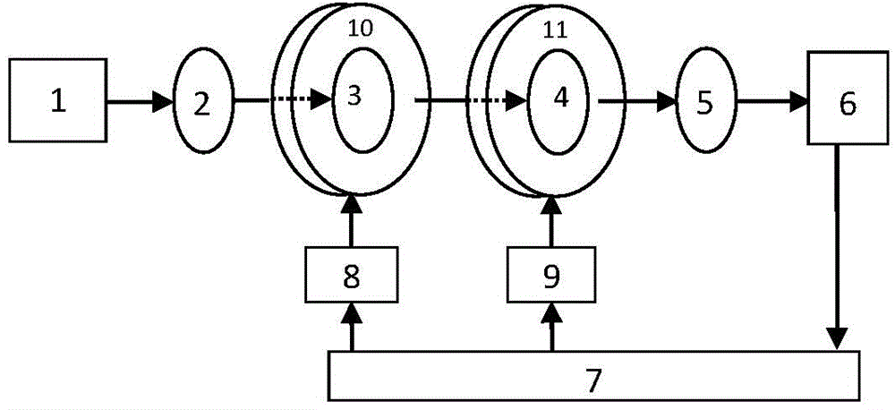
[0048] The structure of the present invention is as figure 1 As shown: including a light source 1 and a computer 7, the parallel natural light emitted by the light source 1 passes through the polarizer 2 placed on the common transmission axis, the first birefringent device to be measured 3, the second birefringent device to be measured 4, and the analyzer 5 Received by the photodetector 6, the first turntable 10 is connected with the first motor 8, and the second turntable 11 is connected with the second motor 9; the computer 7 is connected with the photodetector 6, collects and analyzes the photocurrent data of the photodetector 6, and Feedb...


PUM


Abstract

The invention discloses a device and a method capable of simultaneously detecting the optical axis directions of two birefringence devices. A light beam of a light source is received by a photoelectric detector, the polarization directions of a polarizer and an analyzer are adjusted parallel to each other, and a light current value is collected; a first to-be-detected birefringence device is put into a first rotary table, the first rotary table is rotated to find a position with the maximum light current, the position is marked, a light current value is collected, and the first to-be-detected birefringence device is taken out; a second to-be-detected birefringence device is put into a second rotary table, the second rotary table is rotated to find a position with the maximum light current, the position is marked, and a light current value is collected; the first to-be-detected birefringence device is put into the first rotary table; the first rotary table is rotated to make the marking directions of the first to-be-detected birefringence device and the second to-be-detected birefringence device parallel to each other, and a light current value is collected; the second rotary table is rotated to rotate the second to-be-detected birefringence device by an angle of Pai, and a light current value is collected; and the optical axis directions of the first to-be-detected birefringence device and the second to-be-detected birefringence device are marked according to the collected light current values.

Description

technical field [0001] The invention belongs to the field of polarization optical detection, in particular to a device and method capable of simultaneously detecting the directions of the optical axes of two birefringent devices. Background technique [0002] Birefringent devices made of birefringent materials, such as wave plates or phase retarders (or phase compensators), are basic optical components widely used in optical experiments and optical instruments. In principle, any material with birefringence effect can be used to make birefringent devices, such as crystal phase retarders and liquid crystal phase retarders made of birefringent crystals such as quartz, calcite, magnesium fluoride or mica, etc. Retarders, and magnetic liquids, W sheets, etc. under the action of an external magnetic field. [0003] But no matter what kind of material is used, for the convenience of measurement and use, the optical axis (or equivalent optical axis) of the birefringent device is us...

Claims


Application Information

Patent Timeline
Patent Type & Authority Applications(China)
IPC IPC(8): G01M11/02
Inventor 张璐
Owner SHANDONG UNIV
Why Eureka
Try Eureka