High-speed railway sound barrier insertion loss prediction method of five-sound-source mode

A technology for insertion loss and high-speed railways, applied in noise absorption devices, special data processing applications, instruments, etc., can solve problems such as engineering design difficulties, limited scope of application, difficult noise source distribution characteristics, etc.

Active Publication Date: 2015-08-12
CHINA RAILWAY DESIGN GRP CO LTD
View PDF2 Cites 11 Cited by
  • Summary
  • Abstract
  • Description
  • Claims
  • Application Information

AI Technical Summary

Problems solved by technology

[0003] However, the above methods still have obvious shortcomings when predicting the insertion loss of high-speed railway sound barriers
On the one hand, the actual noise sources of high-speed railways are distributed in a large range from 3m below the rail surface to 5.6m above the rail surface. It is difficult to accurately determine the distribution characteristics of the noise sources only by using the lower and upper equivalent sound sources, and the noise source of the high-speed railway The equivalent frequency and energy ratio are not constants, but are variables related to the train speed. The insertion loss predicted by the existing method is a constan

Method used


Image

  • High-speed railway sound barrier insertion loss prediction method of five-sound-source mode
  • High-speed railway sound barrier insertion loss prediction method of five-sound-source mode
  • High-speed railway sound barrier insertion loss prediction method of five-sound-source mode

Examples


Embodiment 1

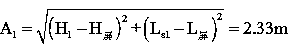
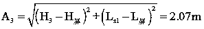
[0081] Village A proposed case: Village A is located near a high-speed railway, and it is a one-story building. The shortest distance from the center line of the outer rail of the line is 30m; The height of the upper edge of the outer side of the wing plate is the elevation of the rail top, and the lower edge of the outer side of the wing plate is 0.9m lower than the top of the railway track; the track surface is 8m above the ground, and the sensitive point is located 1.2m above the ground; it is planned to install a high sound barrier treatment 2.05m above the rail surface Noise, the horizontal distance between the inner side of the sound barrier and the center line of the outer line of the railway is 3.31m; the speed of the train passing through the section to be installed with the sound barrier is 300km / h; the theoretical noise reduction amount of the predicted sound barrier is the insertion loss of the sound barrier.

[0082] The specific calculation steps are as figure 1 ...


PUM


Abstract

The invention discloses a high-speed railway sound barrier insertion loss prediction method of a five-sound-source mode. The method comprises the following steps of equivalently simplifying a high-speed railway noise source into a wheel-rail area noise source, a train body lower part noise source, a train body upper part noise source, a current collection system noise source and a bridge structure noise source according to the composition, position, frequency characteristics and attenuation law of the high speed railway noise source, and respectively calculating the insertion loss of a wing plate for the five sound sources by virtue of a single-sound-source mode; spreading the noise of a wheel-rail area, a train body lower part, a train body upper part, a current collection system and a bridge structure to be superimposed with noise on a sensitive point after a sound barrier is installed, obtaining a main noise grade after the sound barrier is installed, subtracting the main noise grade from the noise grade before the sound barrier is installed, introducing an insertion loss correction item of the bridge wing plate, and obtaining an insertion loss prediction value by adopting the five-sound-source calculation method. By adopting the method, the weaknesses in the traditional sound barrier insertion loss prediction method can be overcome. The high-speed railway sound barrier insertion loss prediction method is applied to the high-speed railway sound barrier engineering design and the ambient noise influence valuation and has the advantages of accurate prediction value and high engineering practicability.

Description

technical field [0001] The invention belongs to the research field of high-speed railway noise control in the subject of environmental engineering, and relates to a method for predicting noise reduction effects of high-speed railway sound barriers, in particular to a method for predicting insertion loss of high-speed railway sound barriers with five sound source modes, which is suitable for high-speed railways Sound barrier engineering design and environmental noise impact assessment. Background technique [0002] The prediction of insertion loss of sound barrier is an important content in the engineering design of high-speed railway sound barrier. In order to predict the theoretical noise reduction of different heights of noise barriers on noise sensitive points, and to determine the reasonable height of high-speed railway noise barriers, the method proposed in the latest research results at home and abroad divides the high-speed railway sound source into upper and lower pa...

Claims


Application Information

Patent Timeline
IPC IPC(8): G06F17/50E01F8/00
Inventor 胡文林刘冀钊胡叙洪王少林
Owner CHINA RAILWAY DESIGN GRP CO LTD
Why Eureka
Try Eureka