A pilot-operated valve needle sealing system

A pilot valve and valve needle technology, which is applied in the field of pilot valve needle sealing system, can solve the problems of not closely matching with the core, burrs on the rubber mouth, and color difference, etc., and achieves long service life, uniform force point, Complete effect of glue mouth

Active Publication Date: 2017-07-28
SUZHOU HTS MOLD
View PDF6 Cites 1 Cited by
  • Summary
  • Abstract
  • Description
  • Claims
  • Application Information

AI Technical Summary

Problems solved by technology

[0002] In order to prevent the existing valve needle and heating core from being directly matched, the high heat of the core is transmitted to the valve needle, which makes the temperature of the head of the valve needle high, and the position of the product glue port has color difference or sun mark, and the valve needle is not in contact with the valve needle. The core fits tightly, leaving a gap of 0.1~0.5mm on one side. Because the hot runner system is in the working state of heating, the hot nozzle and the runner plate will be deformed, and when the valve needle hangs in the hot nozzle, it will be biased to one side. During the sealing process of the needle moving forward, one side of the valve needle head will first contact with the side of the core cover rubber port, resulting in inconsistent stress points on the circular rubber port, and the rubber port will be subjected to multiple unbalanced stresses. Under the impact of force, it becomes an oval rubber mouth, so that the valve needle cannot seal the glue, and there are burrs on the glue mouth of the product

Method used


Image

  • A pilot-operated valve needle sealing system
  • A pilot-operated valve needle sealing system
  • A pilot-operated valve needle sealing system

Examples


Embodiment Construction

[0010] The preferred embodiments of the present invention will be described in detail below in conjunction with the accompanying drawings, so that the advantages and features of the present invention can be more easily understood by those skilled in the art, so as to define the protection scope of the present invention more clearly.

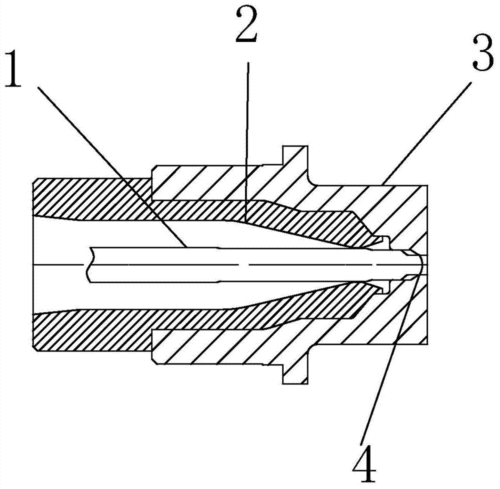
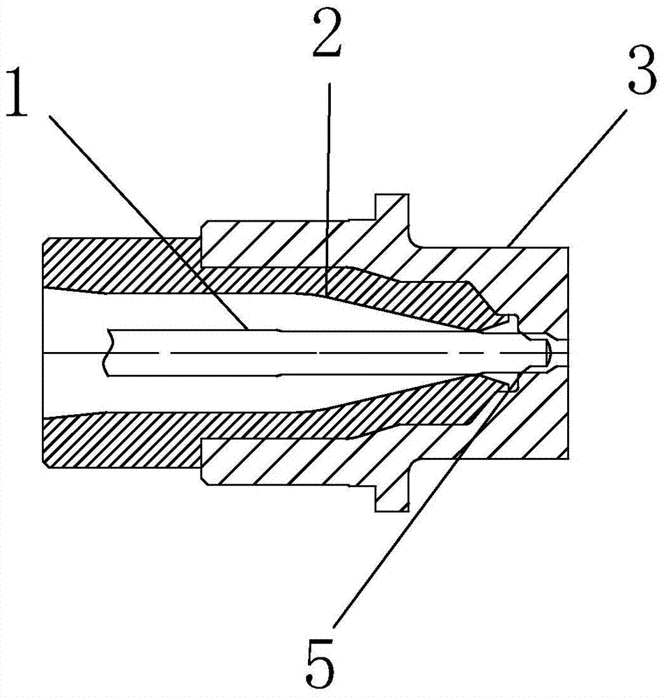
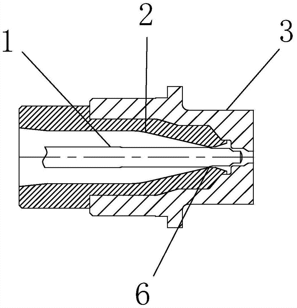
[0011] see figure 1 Only image 3 , the embodiment of the present invention includes:

[0012] A pilot-operated valve needle sealing system, comprising: a valve needle 1, a core 2 and a core cover 3; the core 2 is arranged inside the core cover 3, and the valve needle 1 is arranged inside the core 2; The first step of the head of the valve needle 1 is matched with the circular rubber mouth of the core cover 3, that is, the first step of the core cover 3, and the matching gap is 0.002 to 0.005 mm on one side; the second step of the valve needle 1 5 and the second step of the core cover 3 have a gap fit, and the one side of the fit gap is 0.01 to...


PUM


Abstract

The invention discloses a pilot-operated type valve needle glue sealing system. The system comprises a valve needle, a core and a core cover. The core is arranged in the core cover. The valve needle is arranged in the core. A first step at the head of the valve needle is in a clearance fit relationship with a round glue gate of the core cover. The single edge of the fit gap has the size of 0.002-0.005mm. A second step of the valve needle is in a clearance fit relationship with a second step of the core cover and the single edge of the fit gap has the size of 0.01-0.02mm. A third step of the valve needle is in a clearance fit relationship with the core and the single edge of the fit gap has the size of 0.1-0.2mm. Through the pilot-operated type valve needle glue sealing system, stress points of the head of the valve needle and the round glue gate are uniform, the round glue gate is not changed into an elliptical structure, the valve needle and the round glue gate resist wear and have long service lives, the product glue gate is complete and burr or aberration around the glue gate is not produced.

Description

technical field [0001] The invention relates to an improvement of a valve needle sealing system, in particular to a valve needle head and a circular rubber mouth with uniform stress points, the glue mouth will not become an ellipse, the valve needle and the circular rubber mouth are wear-resistant, and the service life is long. Long, and the product glue mouth is complete, there will be no burrs or color difference around the glue mouth. Pilot valve needle sealing system. Background technique [0002] In order to prevent the existing valve needle and heating core from being directly matched, the high heat of the core is transmitted to the valve needle, which makes the temperature of the head of the valve needle high, and the position of the product glue port has color difference or sun mark, and the valve needle is not in contact with the valve needle. The core fits tightly, leaving a gap of 0.1~0.5mm on one side. Since the hot runner system is in the working state of heatin...

Claims


Application Information

Patent Timeline
Patent Type & Authority Patents(China)
IPC IPC(8): B29C45/28
CPCB29C45/2806
Inventor 沈坚陈再良
Owner SUZHOU HTS MOLD
Why Eureka
Try Eureka