Main shaft box for gantry engraving and milling machine

A spindle box, engraving and milling machine technology, applied in the direction of metal processing machinery parts, large fixed members, metal processing equipment, etc., can solve the problems of low torque, low work efficiency, unsuitable for roughing operations, etc., to increase the roughing capacity , small vibration, and the effect of improving the smoothness

Pending Publication Date: 2020-04-17
惠州市力玛机械设备有限公司
View PDF0 Cites 0 Cited by
  • Summary
  • Abstract
  • Description
  • Claims
  • Application Information

AI Technical Summary

Problems solved by technology

[0003] The purpose of the present invention is to solve the shortcomings of the existing engraving and milling machine spindle box in the prior art that the torq

Method used


Image

  • Main shaft box for gantry engraving and milling machine
  • Main shaft box for gantry engraving and milling machine
  • Main shaft box for gantry engraving and milling machine

Examples


Embodiment Construction

[0018] The following will clearly and completely describe the technical solutions in the embodiments of the present invention with reference to the accompanying drawings in the embodiments of the present invention. Obviously, the described embodiments are only some, not all, embodiments of the present invention.

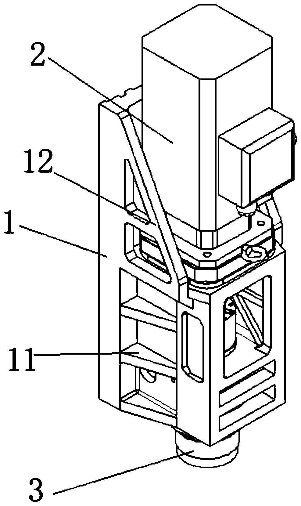
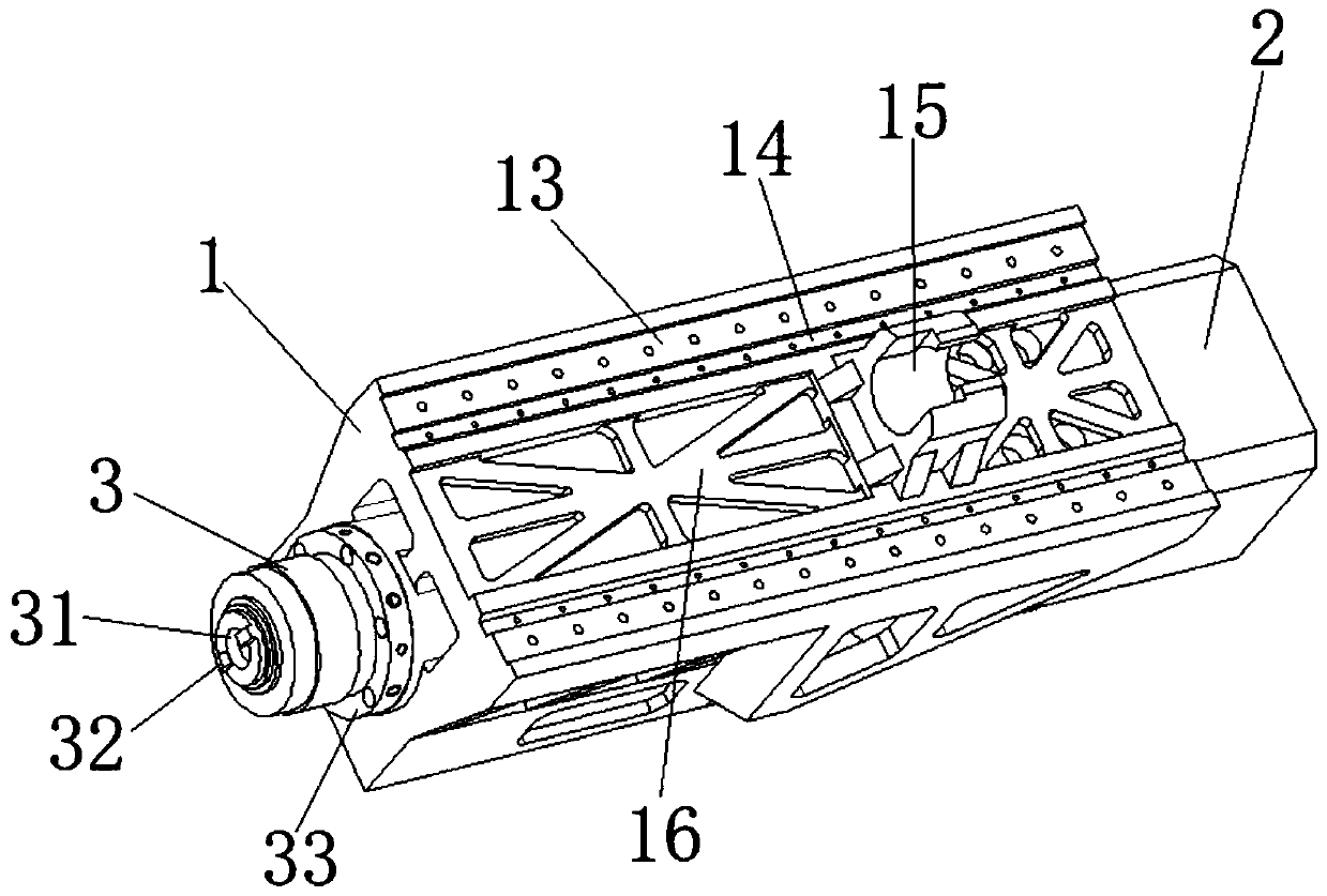
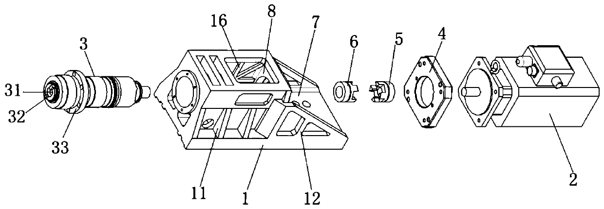
[0019] refer to Figure 1-5 , a spindle box of a gantry engraving and milling machine, including a spindle box 1 slidably connected on the engraving and milling machine door frame, the spindle box 1 includes a hollowed-out motor chamber 7 and a spindle chamber 8, and a guide rail mounting surface 13 arranged on the back of the spindle box 1 , one side of the guide rail mounting surface 13 is symmetrically provided with two guide rail pressing block installation positions 14, and a screw nut seat 15 is fixed between the two guide rail pressing block installation positions 14, and the spindle box 1 is installed in the lead screw nut seat 15 The screw nut assembly and t...


PUM


Abstract

The invention relates to the technical field of engraving and milling machines, in particular to a main shaft box for a gantry engraving and milling machine. The main shaft box for the gantry engraving and milling machine comprises a main shaft box which is connected to a door frame of the engraving and milling machine in a sliding manner; the main shaft box comprises a hollow motor chamber, a main shaft chamber, and a guide rail mounting surface which is arranged on the back of the main shaft box; a plurality of first reinforcing rib plates are symmetrically arranged on the outer wall of themain shaft chamber; second reinforcing rib plates are mounted on the inner wall of the main shaft chamber and the guide rail mounting surface; reinforcing frames are symmetrically arranged on the twosides of the motor chamber; a main shaft servo motor is fixedly arranged in the motor chamber through a main shaft transferring plate and a screw; an output shaft of the main shaft servo motor is in transmission connection with a main shaft; and the main shaft is rotatably connected to the interior of the main shaft chamber through a main shaft mounting flange and another screw. Through an integrated design, the main shaft box for the gantry engraving and milling machine is high in stability, improves the roughing capacity of a machine tool, has practical performance and is suitable for popularizing.

Description

technical field [0001] The invention relates to the technical field of engraving and milling machines, in particular to a spindle box of a gantry engraving and milling machine. Background technique [0002] Engraving and milling machine is a kind of CNC machine tool. The engraving and milling machine is a CNC milling machine that uses small tools, high power, and high-speed spindle motors. The engraving and milling machine can not only engrave, but also mill. It is a high-efficiency and high-precision CNC machine tool. The engraving and milling machine has a wide range of applications, and is widely used in the rough and fine machining of precision mold cores at one time, mold copper electrodes, batch processing of aluminum products, shoe mold manufacturing, fixture processing, and watch industry. Engraving and milling machines are more and more important in the machine tool processing industry because of their high cost performance, fast processing speed, and good finish ...

Claims


Application Information

Patent Timeline
IPC IPC(8): B23B19/02B23Q1/70
CPCB23Q1/70
Inventor 刘小东
Owner 惠州市力玛机械设备有限公司
Why Eureka
Try Eureka