A displacement transmission structure of an inspection robot

An inspection robot and transmission structure technology, applied in the field of inspection robots, can solve the problems of easy noise, high cost, damage to the body, etc., and achieve the effects of prolonging the service life, uniform force points, and free horizontal movement.

Active Publication Date: 2020-08-21
STATE GRID HEBEI ELECTRIC POWER CO LTD
View PDF6 Cites 0 Cited by
  • Summary
  • Abstract
  • Description
  • Claims
  • Application Information

AI Technical Summary

Problems solved by technology

There are also various forms of inspection robots. In the past, ground-type roller walking robots were used to complete the inspection work for inspection robots inside buildings. However, this kind of robot is not careful enough to observe higher positions inside the building. There are always blind spots and omissions that are not observed, and its walking speed is not very fast, and it always collides with objects on the ground, which affects the inspection effect and causes damage to the body; there are also some fixed Although the inspection robot on the top floor of the building has improved many obstacles caused by ground inspection, its singleness of horizontal inspection cannot adjust the inspection with the best view, and when it moves laterally, it will rub against the track It is easy to generate noise, and the excessive length of the lateral traction device will also bring a lot of inconvenience to the inspection robot when moving, and the maintenance is also very difficult and the cost is high

Method used


Image

  • A displacement transmission structure of an inspection robot
  • A displacement transmission structure of an inspection robot
  • A displacement transmission structure of an inspection robot

Examples


Embodiment 1

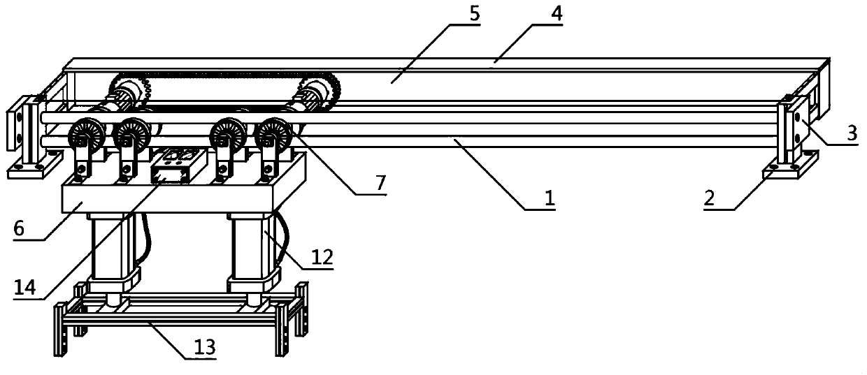
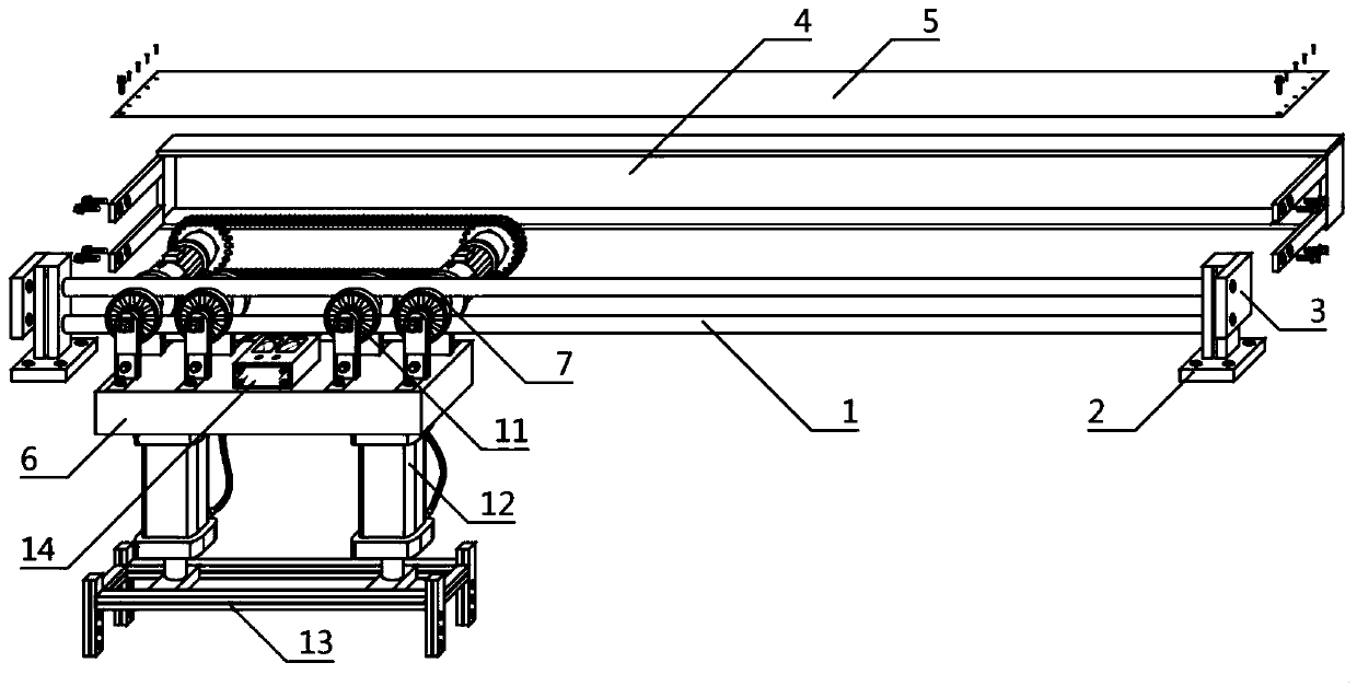
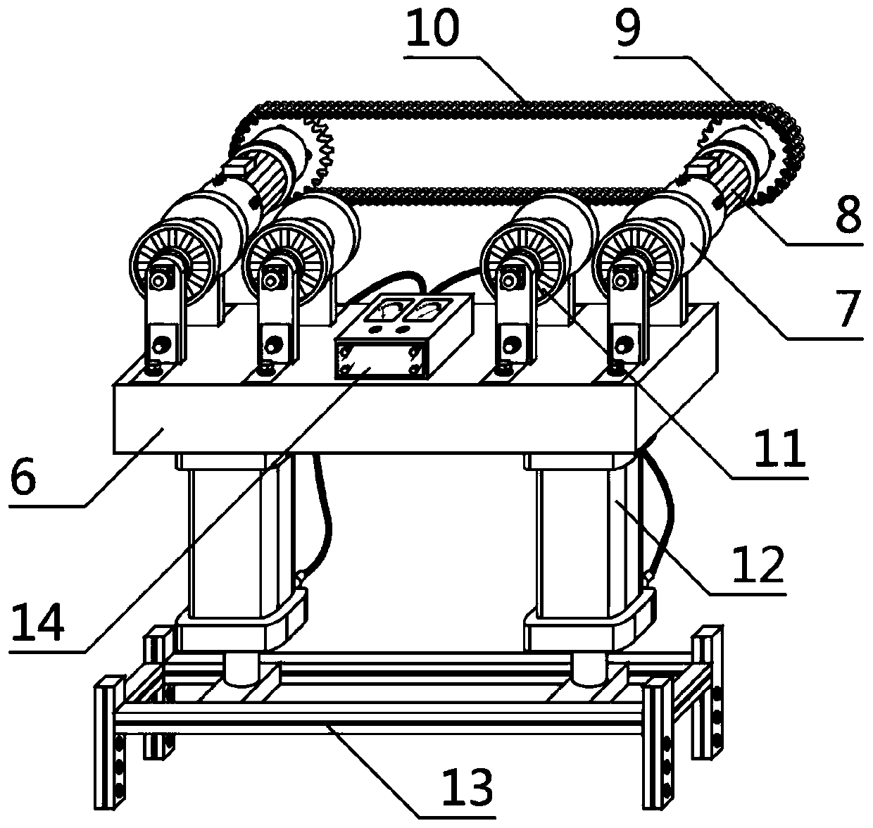
[0026] Such as figure 1 , figure 2 , image 3 , Figure 4 A displacement transmission structure of an inspection robot is shown, which is characterized in that: a horizontal rail frame 1, a transmission protection box 4, a horizontal moving frame 6, several driving pulleys 7, several auxiliary positioning pulleys 11, several lifting devices 12, The inspection device fixing frame 13 and the control box 14 are composed, and the horizontal track frame 1 is also provided with several facade fixing plates 2 and several side fixing plates 3, and any of the facade fixing plates 2 is located on the horizontal track frame 1 The lower part of one side, the facade fixed plate 2 is fixedly connected with the horizontal track frame 1, any of the side fixed plates 3 is located at one side of the horizontal track frame 1, and the side fixed plate 3 and the horizontal track frame 1 are fixed connected, the transmission protection box 4 is located on the other side of the horizontal rail f...

Embodiment 2

[0029] Such as figure 1 , figure 2 , image 3 , Figure 4 A displacement transmission structure of an inspection robot is shown, which is characterized in that: a horizontal rail frame 1, a transmission protection box 4, a horizontal moving frame 6, several driving pulleys 7, several auxiliary positioning pulleys 11, several lifting devices 12, The inspection device fixing frame 13 and the control box 14 are composed, and the horizontal track frame 1 is also provided with several facade fixing plates 2 and several side fixing plates 3, and any of the facade fixing plates 2 is located on the horizontal track frame 1 The lower part of one side, the facade fixed plate 2 is fixedly connected with the horizontal track frame 1, any of the side fixed plates 3 is located at one side of the horizontal track frame 1, and the side fixed plate 3 and the horizontal track frame 1 are fixed connected, the transmission protection box 4 is located on the other side of the horizontal rail f...

Embodiment 3

[0031] Such as figure 1 , figure 2 , image 3 , Figure 4 A displacement transmission structure of an inspection robot is shown, which is characterized in that: a horizontal rail frame 1, a transmission protection box 4, a horizontal moving frame 6, several driving pulleys 7, several auxiliary positioning pulleys 11, several lifting devices 12, The inspection device fixing frame 13 and the control box 14 are composed, and the horizontal track frame 1 is also provided with several facade fixing plates 2 and several side fixing plates 3, and any of the facade fixing plates 2 is located on the horizontal track frame 1 The lower part of one side, the facade fixed plate 2 is fixedly connected with the horizontal track frame 1, any of the side fixed plates 3 is located at one side of the horizontal track frame 1, and the side fixed plate 3 and the horizontal track frame 1 are fixed connected, the transmission protection box 4 is located on the other side of the horizontal rail f...


PUM


Abstract

The invention aims at providing a patrolling robot displacement transmission structure. According to the technical scheme, the patrolling robot displacement transmission structure is composed of a horizontal track frame, a transmission protection box, a horizontal motion frame, two drive sliding wheels, two auxiliary positioning sliding wheels, two lifting devices, a patrolling device fixing frameand a control box. Each of the two sides of the horizontal track frame is provided with a vertical face fixing plate and a side face fixing plate. The transmission protection box is provided with a cover plate. Each drive sliding wheel is provided with a drive motor, a transmission gear and a transmission chain. According to the mechanism, the hoisting type transmission structure in which the sliding wheels are utilized for fixing and moving, and self movement direction and position displacement control of a patrolling robot can be achieved is adopted; the structure is simple, installation isconvenient, the space used area is small, and components and parts are convenient to detach and replace. The integral horizontal movement and vertical movement stability is higher, displacement is more accurate, noise is low, a short and quiet linkage mechanism is more environment-friendly, the robot patrolling work in various spaces can be finished, and more stability and safety are achieved.

Description

technical field [0001] The invention relates to the field of inspection robots, in particular to a displacement transmission structure of an inspection robot. Background technique [0002] Today, the trend of "replacing human beings with machines" is being further advanced, not only in the field of production, but also in the field of life and service, and the application of robots is becoming more and more extensive. With the continuous advancement of science and technology, various forms of robots have also been put on the market in large quantities. Among them, the use of inspection robots is the most common one, especially in terms of electricity. This kind of robots is the most common. , my country's smart grid construction has entered a new stage of comprehensive and rapid development, so the demand for inspection work in this field is also very large. It is involved, although the coverage is relatively small, but this is undoubtedly the trend and direction of future de...

Claims


Application Information

Patent Timeline
Patent Type & Authority Patents(China)
IPC IPC(8): B25J5/02B25J19/00
CPCB25J5/02B25J19/00
Inventor 王长宁张益辉唐亮陈瑞华孙玲李世猛张彦瑞王飞何利平郭家伟沈锐
Owner STATE GRID HEBEI ELECTRIC POWER CO LTD
Why Eureka
Try Eureka