An engine electric heating system and control method

A control method and engine technology, applied to engine components, engine starting, machine/engine, etc., can solve problems such as carbon deposition in heaters, reduced heating and heating efficiency, and inconvenient heating operations, so as to reduce intermediate heat exchange links, improving utilization efficiency, and high energy utilization

Inactive Publication Date: 2016-09-28
PLA ARMORED FORCE TECH COLLEGE
View PDF7 Cites 0 Cited by
  • Summary
  • Abstract
  • Description
  • Claims
  • Application Information

AI Technical Summary

Problems solved by technology

2) Poor heating effect
Due to the simple structure of the heater, the thermal combustion efficiency of the heater is low, the heating and thermal cycle effect is poor, the different parts of the heating system are heated unevenly, and the parts are easily overheated, and the engine heating effect is poor, which is not conducive to engine starting
3) Inconvenient heating operation, high failure rate, fixed heating mode, uncontrolled heating process, and poor environmental adaptability
The fuel atomization and working medium heat exchange conditions are fixed, and the heater works at a fixed air-fuel ratio and heat exchange rate. When the ambient temperature and air pressure change, the heating efficiency decreases, and it is difficult to meet the heating requirements of typical environments in cold regions.
Secondly, in terms of control, the heating process of the heater is currently uncontrollable, and the heating mode is fixed. It is impossible to adjust the working mode of the heater according to the temperature environment of the vehicle and changes in the altitude and air pressure environment, and automatically adjust the fuel injection combustion of the heater. and heat exchange rate
Thirdly, in terms of operation, the current heater is manually operated, and the heating process cannot be monitored in real time. In a low-temperature and low-oxygen environment, the heater has serious carbon deposits and many faults

Method used


Image

  • An engine electric heating system and control method
  • An engine electric heating system and control method
  • An engine electric heating system and control method

Examples


Embodiment Construction

[0036] The present invention will be further described in detail below in conjunction with the accompanying drawings, so that those skilled in the art can implement it with reference to the description.

[0037] A specific embodiment of the present invention is described by taking an in-line four-cylinder engine as an example.

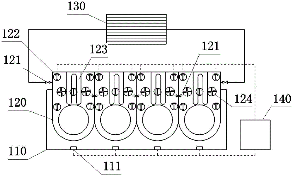
[0038] Such as figure 1 As shown, the present invention provides an engine electric heating system, which includes a cylinder water jacket 120 arranged outside the cylinder of the engine 110 . The cylinder water jacket 120 is equipped with cooling water, and the cylinder water jacket 120 exchanges heat with the engine 110 through the cooling water. A cylinder water jacket 120 is independently provided outside each cylinder of the engine 110 , that is, for an inline four-cylinder engine, four cylinder water jackets 120 are provided in total, and each cylinder water jacket 120 exchanges heat with one cylinder. An electric control valve 121 is arranged ...


PUM


Abstract

The invention discloses an engine electric heating system, which comprises a cylinder water jacket independently arranged outside each cylinder of the engine, an electric heating pipe arranged in the cylinder water jacket, an engine water tank, a water temperature sensor, an engine temperature detector and a controller. The water temperature sensor is arranged in the cylinder water jacket to detect the water temperature of the cooling water in the cylinder water jacket. The engine temperature detector is arranged on each cylinder of the engine to detect the temperature of each cylinder. The controller can , the temperature measured by the engine temperature detector controls the heating capacity of the electric heating tube. The engine electric heating system provided by the invention heats the cooling water by directly installing an electric heating pipe in the water jacket of the cylinder, which reduces intermediate heat exchange links and greatly improves energy utilization efficiency. The cylinder water jacket is arranged separately, so that the engine is heated evenly, reduces the temperature gradient of the engine, and protects the engine.

Description

technical field [0001] The invention relates to the technical field of automobile engine preheating, in particular to an engine electric heating system and a control method. Background technique [0002] In the cold regions of Northeast and Northwest plateaus in my country, the winter time is long, the temperature and air pressure are low, and the air contains little oxygen. In this low-temperature and low-oxygen environment, it is difficult or impossible to start the engine of a heavy-duty vehicle. Therefore, preheating must be carried out before starting to ensure that the engine has good starting conditions, ensure the smooth start of the engine, reduce starting wear and prolong the service life of the vehicle. [0003] At present, heaters are installed on heavy-duty vehicles in cold regions for preheating and heating before starting, but these heaters follow the traditional structure with fixed heating modes, low efficiency, poor heating effect, and long heating time. P...

Claims


Application Information

Patent Timeline
Patent Type & Authority Patents(China)
IPC IPC(8): F02N19/10F02F1/16
CPCF02F1/14F02N19/10F02N2200/023
Inventor 王加雪张建国陈永和黄永生杨柏春余正根秦宝站周鑫张洪才宋咸斌唐雪松
Owner PLA ARMORED FORCE TECH COLLEGE
Why Eureka
Try Eureka