Electric conduction rail type mounting assembly

A technology for installing components and conductive tracks, which is applied to the components of lighting devices, lighting devices, circuit layout, etc., can solve the problems of long installation time, high installation cost, difficult to replace, etc., and achieves light and simple overall structure, manufacturing and installation. Low cost, clever setup and transition effects

Inactive Publication Date: 2015-08-19
惠州市梧桐实业有限公司
View PDF7 Cites 9 Cited by
  • Summary
  • Abstract
  • Description
  • Claims
  • Application Information

AI Technical Summary

Problems solved by technology

[0003] The purpose of the present invention is to provide a conductive track type installation assembly, which solves the problem that the installation assembly used to install advertising light boxes, advertising machines and lamps in the prior art is not easy to replace, has a single function, and complicated installation, which leads to long installation time and high installation cost. question

Method used


Image

  • Electric conduction rail type mounting assembly
  • Electric conduction rail type mounting assembly
  • Electric conduction rail type mounting assembly

Examples


Embodiment 1

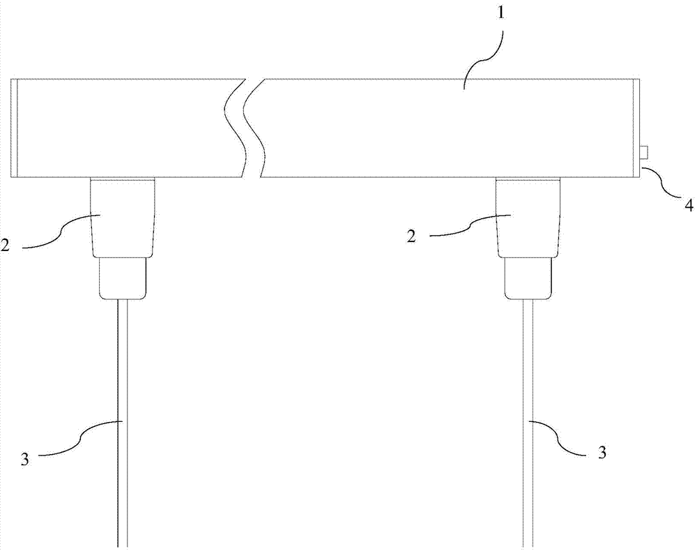
[0045] There is one suspension assembly 2, and a single suspension assembly 2 draws positive current and negative current respectively.

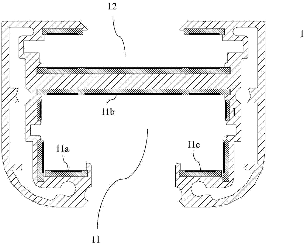
[0046] Specifically, as figure 2 As shown, the first electrode 11a is set on the left bottom wall in the first rail 11, the third electrode 11c is set on the right bottom wall, and the second electrode 11b is set on the top wall. Figure 5-6 The first flat-head screw 22a is the touch piece that conducts the first electrode 11a. Unscrew the first flat-head screw 22a and make contact with the first electrode 11a. The first through hole 230a of the first insulating rubber seat 23a is located in the second through hole. Below the hole 230b, the lowermost end of the first insulating rubber seat 23a abuts against the first flat head 220a of the first flat head screw 22a, so that the first flat head screw 22a is in stable contact with the first electrode 11a, and conducts the first electrode. 11a, and the first electrode current is passed to the ...

Embodiment 2

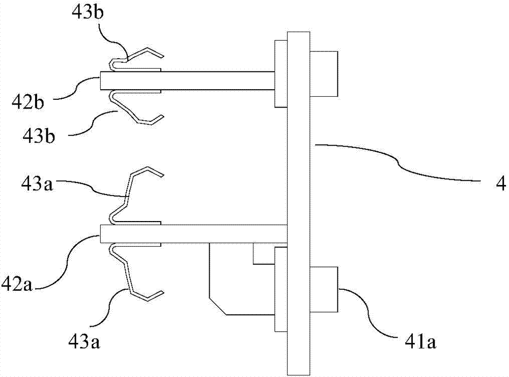
[0051] The difference from Embodiment 1 is that the first flat-head screw 22a is separated from the first electrode 11a, and the first electrode 11a is not connected. The specific structure is the same as that of the second flat-head screw 22b and the second glue seat 23b is the same; at the same time, the second flat-head screw 22a is in contact with the third electrode 11c, and conducts the current of the third electrode 11c. The grub screw 22b guides the current of the third electrode 11c to the conductive base 21, and then guides the current from the conductive base 21 to the conductive connecting pipe 26 as an external electrode; the same as the embodiment 1, the contact element in contact with the second electrode 11b is Sliding column 24, and sliding column 24 is the conductive column that is made of metal, then derives the second electrode current by conductive column, and the second electrode current is passed to wire 3, as external electrode, so the second electrode c...

Embodiment 3

[0055] The difference from Embodiment 1 is that, in addition to the first flat-head screw 22a being in contact with the first electrode 11a as a contact, the second flat-head screw 22b is also in contact with the third electrode 11c as a contact, and the second flat-head screw The contact structure of 22b is the same as that of the first flat-head screw 22a and the first insulating rubber seat 23a, the first electrode current derived from the first flat-head screw 22a and the second electrode current derived from the second flat-head screw 22b together serve as positive current, and are conducted to the conductive base 21, and then conducted to the conductive connecting pipe 26 by the conductive base 21 as an external electrode; the same as in Embodiment 1, the contact element in contact with the second electrode 11b is a sliding column 24, and the sliding column 24 If it is a conductive column made of metal, the second electrode current is derived from the conductive column as...


PUM


Abstract

The invention relates to an electric conduction rail type mounting assembly which comprises a guide rail and at least one hanging assembly connected to the guide rail in a sliding mode. The guide rail is provided with a first rail body allowing the hanging assembly to slide thereon. The first rail body is internally provided with at least two electrodes. All the hanging assemblies comprise touch pieces for current breakover and corresponding to all the electrodes. The hanging assemblies in the electric conduction rail type mounting assembly can conduct breakover as well as hanging heavy objects, the positive electrodes and the negative electrodes are set and converted very cleverly and conveniently, the hanging assemblies can move on the guide rail, the interval can be adjusted freely, the electric conduction rail type mounting assembly is very suitable for mounting advertising lamp boxes, advertising machines, lamps and the like in public places and households, and lighting lamps can be arranged on the guide rail so that the electric conduction rail type mounting assembly can be widely applied to lighting of industrial production places, shop shopwindows, counters and the like; furthermore, the inner side of the guide rail can be provided with a plurality of electrodes, and different low-voltage direct current and low-voltage alternating current can be provided according to the requirements.

Description

technical field [0001] The invention relates to the technical field of lamp installation, and more specifically relates to a conductive track type installation assembly. Background technique [0002] In the prior art, advertising media such as advertising light boxes and advertising machines are often seen in public places such as exhibition halls, shopping malls, theaters, hotels, and stations. The general installation methods of these advertising media are: fixed on the wall with a bracket or fixed to the ceiling. This fixing method makes it difficult for these facilities to be replaced once they are installed, and consumes man-hours and materials. In addition, the fixed bracket and the power cord leak outside, which affects the aesthetic effect. Contents of the invention [0003] The purpose of the present invention is to provide a conductive track type installation assembly, which solves the problem that the installation assembly used to install advertising light box...

Claims


Application Information

Patent Timeline
Patent Type & Authority Applications(China)
IPC IPC(8): F21V21/35
CPCF21V21/34F21V21/35F21V17/12F21V17/162F21V23/06
Inventor 苗光夫
Owner 惠州市梧桐实业有限公司
Why Eureka
Try Eureka