Windproof sliding simulation system for crane under circumstance of deviation of center of gravity

A technology that deviates from the center of gravity and simulates the system. It is applied to the testing of machines/structural components, measuring devices, and instruments. It can solve the problems of inability to do complex detection, limited detection movement, and limited pushing force, length, and duration of the basic platform, etc. question

Inactive Publication Date: 2015-08-19
SUZHOU ZHONGZHOU ANBO CRANE
6 Cites 0 Cited by

AI-Extracted Technical Summary

Problems solved by technology

[0005] The patent name is: Invention patent of indoor test and detection device for wind-resistant and anti-skid brakes of port cranes, ZL201210104398.4, which discloses that the technical solution adopts vertical loading cylinders, whi...

Method used

In counterweight 4 fixed seats, counterweight 4 can be fixedly set, and several counterweights 4 fixed seats are evenly distributed on the carrying platform 8. The total weight of the counterweight 4 can simulate the sum of the weight of the crane and the load of the crane, and the adjustment of the counterweight 4 can simulate the change of the load weight of the crane. The counterweight 4 fixing seats at different positions arrange the counterweight 4 at various positions to simulate the change of the center of gravity of the crane, so that the effect of overturning, derailment and braking can be simulated under certain moving speed conditions and emergency braking condition...

Abstract

The invention relates to a windproof sliding simulation system for a crane under a circumstance of a deviation of the center of gravity. The system includes two parallel tracks and a test trolley, two of four rollers that the test trolley is provided with are arranged on one of the two tracks, the other two rollers are arranged on the other track, the system also includes an elastic traction device, an interval of the two tracks is adjustable, a carrying platform arranged at the upper part of the test trolley is provided with a telescopic structure in a width direction, a plurality of balancing weight fixing seats are arranged on the carrying platform, and braking devices are arranged on the rollers. Weight is added to a vertical direction of the test trolley by adoption of the balancing weights, and a load of the crane is simulated, compared with adoption of an oil cylinder in the vertical direction to perform pressurization, the structure is simplified, and movement of the test trolley is not excessively restricted; flexible tractive force is applied to the test trolley by adoption of traction chains; and the structure of the guide rails with an adjustable relative interval and the telescopic carrying platform enables the test trolley to simulate brake performance, overturn tendency and the like of portal cranes of different widths.

Application Domain

Structural/machines measurement

Technology Topic

Gantry craneEngineering +6

Image

  • Windproof sliding simulation system for crane under circumstance of deviation of center of gravity
  • Windproof sliding simulation system for crane under circumstance of deviation of center of gravity

Examples

  • Experimental program(1)

Example Embodiment

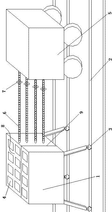
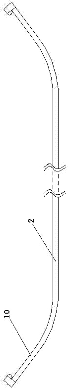
[0021] The present invention will now be described in further detail with reference to the drawings and embodiments. These drawings are simplified schematic diagrams, which only illustrate the basic structure of the present invention in a schematic manner, and therefore only show the constitutions related to the present invention.
[0022] Such as figure 1 with figure 2 As shown, a simulation system for wind-proof sliding when the crane's center of gravity is deviated includes: two parallel rails 2 and a test trolley 1. The four rollers 3 of the test trolley 1 are arranged on two rails 2 in pairs. , It also includes an elastic traction device, the distance between the two rails 2 can be adjusted, the loading platform 8 provided on the upper part of the test trolley 1 is provided with a telescopic structure 9 in the width direction, and the loading platform 8 is provided with several counterweights 4 fixing seats , The roller 3 is provided with a braking device. Four rollers 3 are respectively arranged on two parallel tracks 2 to simulate the form and structure of a crane, and the elastic traction device simulates the comprehensive force of wind on the crane under different weather conditions. The part of the effective windward area of ​​the crane blown by the wind, that is, the elastic traction device is used for traction to simulate the wind force on the effective windward area of ​​the crane. It should be pointed out that the effective windward area is exposed by the crane perpendicular to the track 2. area.
[0023] The counterweight 4 mode is used to increase the weight of the test trolley 1 in the vertical direction, which simulates the lifting load of the crane. Compared with the vertical pressure using a cylinder to pressurize, the structure is greatly simplified, and the movement of the test trolley 1 is also tested. It will not be subject to too many restrictions; the use of the traction chain 6 mode can apply flexible traction to the test trolley 1, such as continuous uninterrupted traction, long-distance traction, traction under dynamic conditions, and the traction force can also be dynamically adjusted at any time The structure formed by the two guide rails with adjustable relative spacing and the carrying platform 8 with retractable width enables the test trolley 1 to simulate the braking performance, overturning tendency, etc. of gantry cranes of different widths.
[0024] The counterweight 4 can be fixedly arranged in the counterweight 4 fixing seat, and several counterweight 4 fixing seats are evenly distributed on the carrying platform 8. The total weight of the counterweight 4 can simulate the sum of the weight of the crane and the crane load, and the adjustment of the counterweight 4 can simulate the change of the crane load weight. The counterweight 4 fixed seat in different positions arranges the counterweight 4 at each position to simulate the change of the center of gravity of the crane, so that the overturning effect, derailment effect and braking can be simulated under certain moving speed conditions and emergency braking conditions The effect is even better, in which under the condition of eccentric gravity, it is easy to cause the roller 3 on one side of the track 2 to bear greater braking pressure.
[0025] The elastic traction device is located in front of the moving direction of the test trolley 1. The elastic traction device is provided with a tractor 5. A number of traction chains 6 are connected to the tractor 5. One end of the traction chain 6 is detachably connected to the test trolley 1. The effective windward area of ​​the crane is divided into different wind-loaded areas, and each wind-loaded area simulates the force of the corresponding crane on the windward area of ​​this position, so that each wind-loaded area is tested against the wind After additional testing, it is possible to specifically propose a comprehensive braking scheme in which all rollers 3 adopt different braking forces.
[0026] The traction direction of the tractor 5 is parallel to the track 2 or the angle is 0-90°, so that the elastic traction device can simulate the anti-overturning tendency and braking ability of the crane under different wind conditions.
[0027] A tension sensor 7 is provided on the traction chain 6. In this way, different internal tensions of the traction chain 6 can be set according to the wind conditions on each wind load area, and at the same time, the corresponding traction chain 6 is tightened according to the set internal tension. The elastic properties of the traction chain 6 can provide traction with a buffering method, and this force time is softer on the test vehicle 1 and can soften the traction between the tractor 5 and the test vehicle 1.
[0028] The tension sensor 7 can set the rated tension value. During the test, the actual traction value of the tractor 5 on the traction chain 6 always fluctuates around the rated tension value, and the floating interval is less than 5% of the weight of the test trolley 1.
[0029] The traction chain 6 is an elastic rope or spring, so that in the dynamic traction process, the tractor 5 can adjust the traction speed in time according to the difference between the actual traction force and the rated traction force set by the tension sensor 7 to ensure that the actual traction force is between the rated traction force The size of the difference is kept within a certain range.
[0030] The braking device is a windproof iron wedge brake or/and a wheel brake. Different braking devices can be installed on the roller 3 at different positions. When the test vehicle 1 is under different stress conditions and different positions and speeds, each The braking device and the braking effect of each roller 3 as well as the overall braking effect and braking time aging can all be simulated. At the same time, through the above comprehensive simulation, a comprehensive braking scheme for the crane under different conditions can be provided.
[0031] Both ends of the track 2 are equipped with upwardly curved arc structures 10, which can prevent the test trolley 1 from being pulled to the outside of the end of the track 2 due to the excessively fast running speed or excessive traction during the test. , In a derailment accident.
[0032] The track 2 is installed in a track groove on the ground, and there are several parallel track grooves on the ground. This technical solution can help adjust the distance between the two tracks 2.
[0033] The four rollers 3 are equipped with wheel pressure sensors. By observing and reading the pressure values ​​of the wheel pressure sensors, it is possible to effectively record the stress value between each roller 3 and the track 2 under various test conditions. Under certain circumstances, the wheel pressure of the four rollers 3 at the same time can determine the overturning tendency and overturning risk.
[0034] The test system also includes a height column arranged on the loading platform 8 on the test rig 1, and a number of counterweights 4 can be fixedly arranged in the vertical direction on the height column, and the counterweights 4 are arranged in the vertical direction. Simulate the weight of the crane in the vertical direction, so that the simulated overturning effect is better under certain moving speed conditions and under emergency braking conditions.
[0035] The above is based on the ideal embodiment of the present invention as inspiration. Through the above description, relevant personnel can make various changes and modifications within the scope of the technical idea of ​​the present invention. The technical scope of the present invention is not limited to the content of the specification, and the technical scope must be determined according to the scope of the claims.

PUM

no PUM

Description & Claims & Application Information

We can also present the details of the Description, Claims and Application information to help users get a comprehensive understanding of the technical details of the patent, such as background art, summary of invention, brief description of drawings, description of embodiments, and other original content. On the other hand, users can also determine the specific scope of protection of the technology through the list of claims; as well as understand the changes in the life cycle of the technology with the presentation of the patent timeline. Login to view more.
Why Eureka
Try Eureka