
Driving device

A driving device and a driven technology, which is applied to the transmission device, gear transmission device, transmission device parts, etc., can solve the problem of decreased controllability, and achieve the effect of improving assembly and mitigating impact force

Inactive Publication Date: 2007-01-10
HONDA MOTOR CO LTD
View PDF1 Cites 1 Cited by
  • Summary
  • Abstract
  • Description
  • Claims
  • Application Information

AI Technical Summary

Problems solved by technology

[0004] In the above-mentioned existing literature, the force acting on the meshing surface of the worm and the worm wheel when the rotation of the worm wheel is restricted can be alleviated by the coil spring, but the elastic force of the coil spring will also act on the worm even in the non-rotation restricted state. Possibility of deterioration of controllability of the driven part due to the operation of the electric motor

Method used

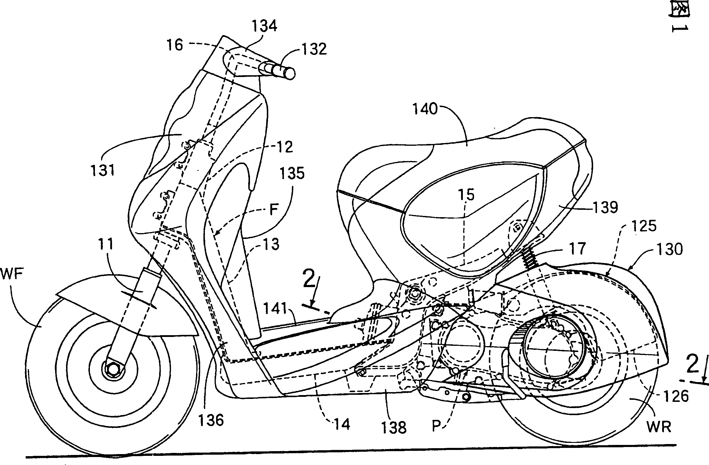
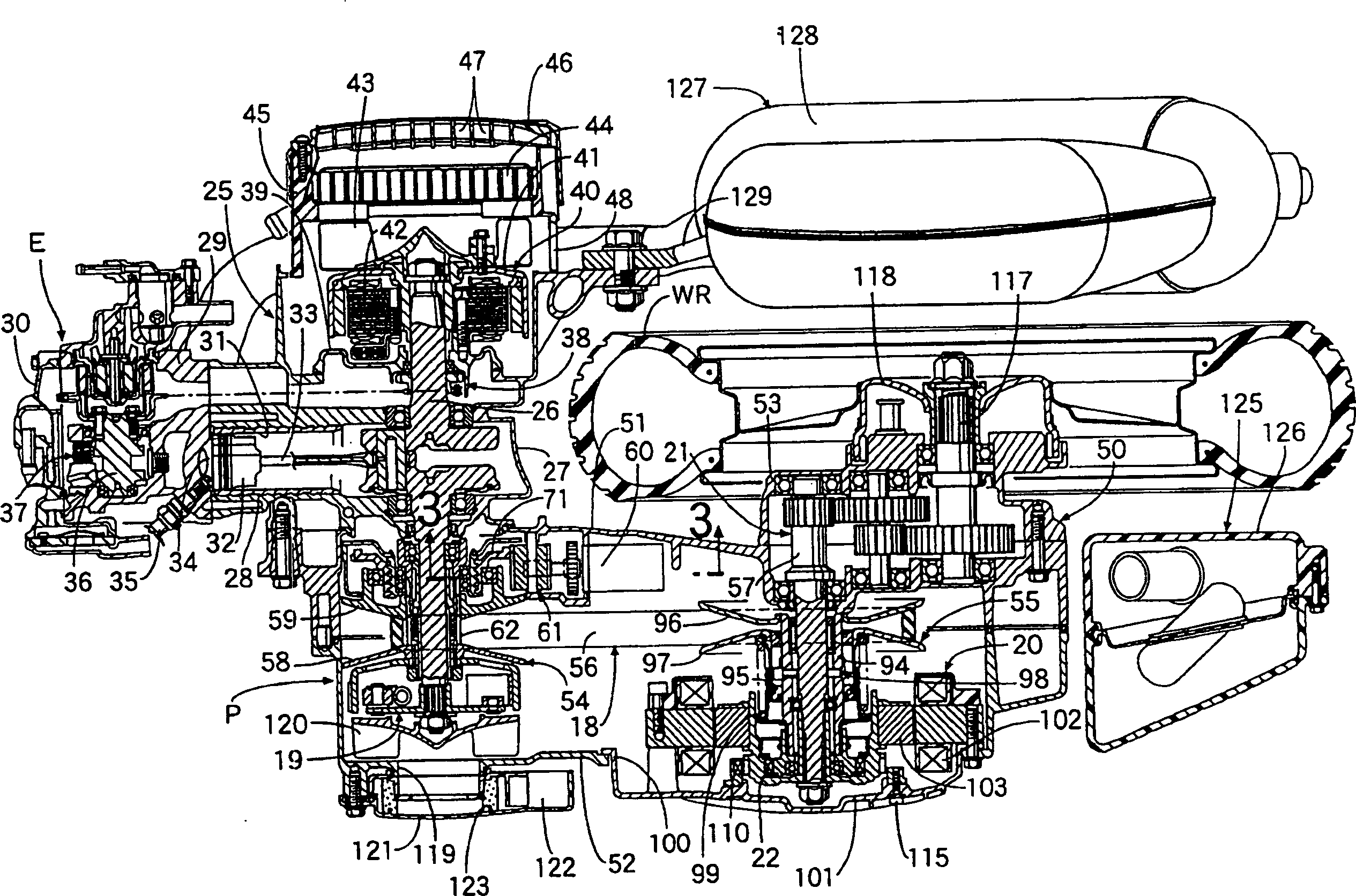

Image

  • Driving device
  • Driving device
  • Driving device

Examples


no. 2 Embodiment

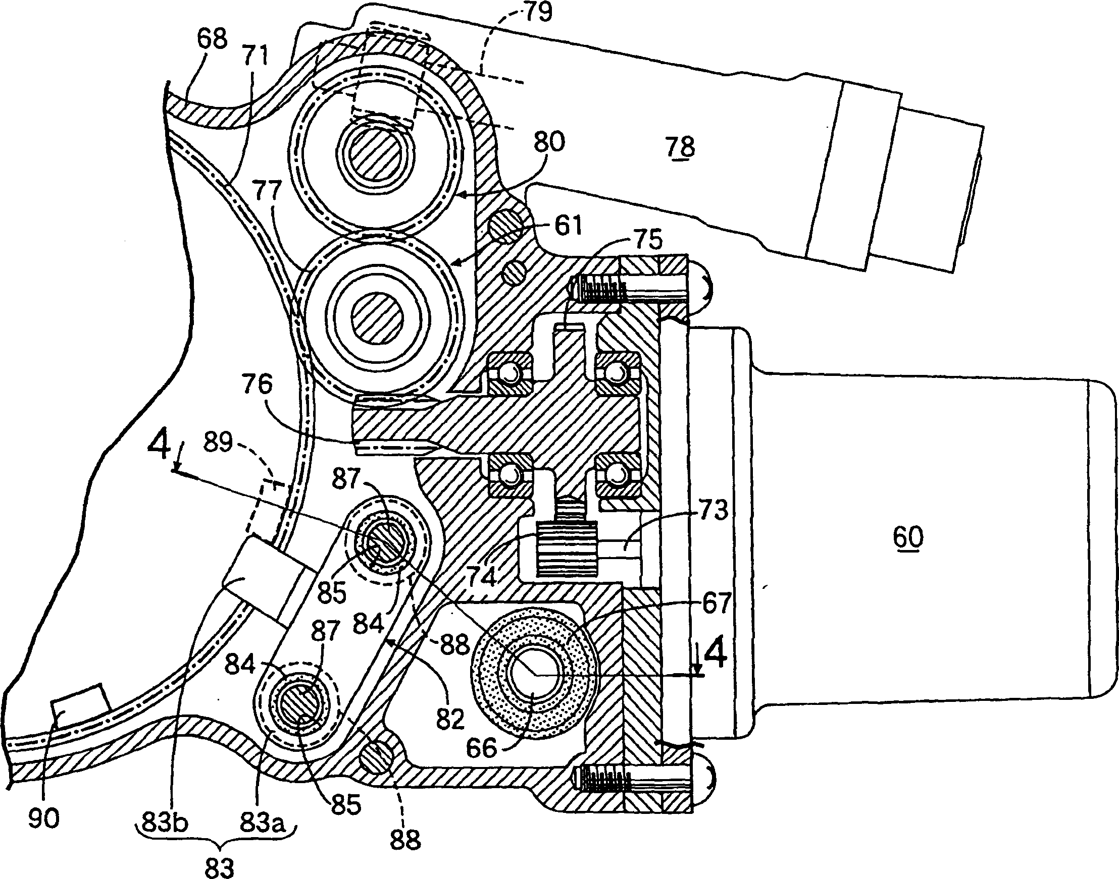
[0081] In the second embodiment, like the above-mentioned first embodiment, the impact force caused by the contact between the sliding gear 71 and the stopper 145 is alleviated by the elastic force of the elastic member 146, so that the impact force can be avoided from acting on the gear transmission mechanism 61 ( Referring to the gear meshing surface in the first embodiment), and because the elastic force of the elastic member 146 acts on the gear transmission mechanism 61 only when the movement of the sliding gear 71 is limited, it will not affect the controllability of the normal rotation control state .

[0082] Fig. 11 is the vicinity of the operating position limiting mechanism of the third embodiment of the present invention and Figure 9 The corresponding cross-sectional view, Figure 12 It is a cross-sectional view taken along line 12-12 in FIG. 11, and parts corresponding to the above-mentioned first and second embodiments are given the same reference numerals and ...

no. 3 Embodiment

[0087] In the third embodiment, like the above-mentioned first and second embodiments, the impact force caused by the contact between the sliding gear 71 and the stopper 153 is alleviated by the elastic force of the elastic member 154, so that the impact force can be avoided from acting on the gear transmission. The gear meshing surface in the mechanism 61 (refer to the first embodiment), and because the elastic force of the elastic member 154 acts on the gear transmission mechanism 61 only when the movement of the sliding gear 71 is limited, it will not affect the normal rotation control state of control.

[0088] Moreover, since the axis is parallel to the axis of the slide gear 71 and is provided in the insertion hole 155 on the stopper 153 , the bolt 158 ​​that passes through the inner surface of the insertion hole 155 with a gap 159 and is threadedly engaged with the box 68 , so that the impact force caused by the contact between the sliding gear 71 and the stopper 153 ca...


PUM


Abstract

To prevent impulsive force from acting on a gear engaging surface of a gear-type transmission means, when the operation at a predetermined operation position of a driven member is regulated, without affecting the operation controllability of the driven member, in a driving device that includes the gear-type transmission means provided between the driven member, which is supported so as to be freely operated on a casing, on which an electric motor is mounted, and the electric motor, and an operation position regulation means provided on the casing to regulate the operation position of the driven member. The operation position regulation means 82 comprises a stopper 83 that abuts against the driven member 71 at its predetermined operating position of the driven member 71 is supported in a floating state to a casing 68 with an elastic member 84, provided between the stopper and the casing 68.

Description

technical field [0001] The present invention relates to a driving device. A gear type transmission mechanism is provided between a driven part freely operatively supported on a box equipped with an electric motor and the electric motor. The operating position limiting mechanism of the operating position of the component. Background technique [0002] For example, in the drive device known from Patent Document 1, when the drive device performs the rotation limitation of the worm wheel corresponding to the rotation of a predetermined angle, in order to avoid the meshing surface of the worm coaxially connected to the electric motor and the worm wheel meshing with the worm The impact force is applied, and a coil spring for relieving the axial movement of the worm wheel is installed between the worm wheel shaft and the case. [0003] Patent Document 1: Japanese Patent Application Laid-Open No. 2003-348791. [0004] In the above-mentioned existing literature, the force acting on...

Claims


Application Information

Patent Timeline
Patent Type & Authority Applications(China)
IPC IPC(8): H02K5/24H02K7/116B62M9/12B62M23/02F16F7/00F16H1/16F16H9/18F16H25/20F16H57/02F16H57/023F16H57/028H02K7/06
CPCB62K11/00H02K5/24H02K7/116
Inventor 塚田善昭大关孝饭室昭宏中村一彦小泽圣二井本丰
Owner HONDA MOTOR CO LTD
Learn More