Damping steel bar cutting device used for constructional engineering

A construction engineering and cutting device technology, which is applied in the field of shock-absorbing steel bar cutting devices for construction engineering, can solve problems such as low work efficiency, worker injury, and lack of fixed steel bars, so as to improve safety and work efficiency, reduce vibration, increase The effect of work efficiency

Inactive Publication Date: 2020-01-17
湖北恩众建筑工程有限公司
View PDF0 Cites 1 Cited by
  • Summary
  • Abstract
  • Description
  • Claims
  • Application Information

AI Technical Summary

Problems solved by technology

[0003] In order to facilitate the construction efficiency of workers, many existing steel bar cutting equipment already have portable functions. Although portable steel bar cutting equipment is convenient for workers to use, some existing portable steel bar cutting equipment lacks the function of fixing steel bars. When workers use this portable steel bar cutting equipment to cut steel bars, they need to fix the steel bars first. For convenience, many workers usually step on the steel bars directly with their feet to prevent the steel bars from shifting during cutting. There is a risk of injury, which leads to the problem that some existing shock-absorbing steel bar cutting devices for construction projects lack the function of fixing steel bars. The existing equipment has poor shock-absorbing effects, especially in construction sites where the ground is not very flat, making the work efficiency not high.

Method used


Image

  • Damping steel bar cutting device used for constructional engineering
  • Damping steel bar cutting device used for constructional engineering
  • Damping steel bar cutting device used for constructional engineering

Examples


Embodiment Construction

[0016] The following will clearly and completely describe the technical solutions in the embodiments of the present invention with reference to the accompanying drawings in the embodiments of the present invention. Obviously, the described embodiments are only some, not all, embodiments of the present invention. Based on the embodiments of the present invention, all other embodiments obtained by persons of ordinary skill in the art without making creative efforts belong to the protection scope of the present invention.

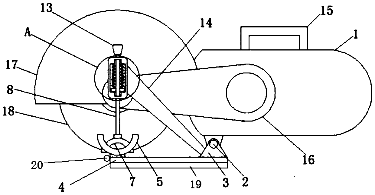
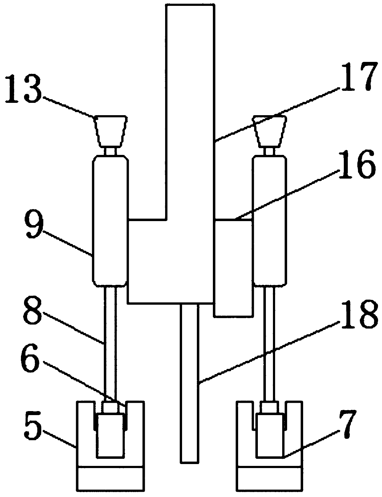
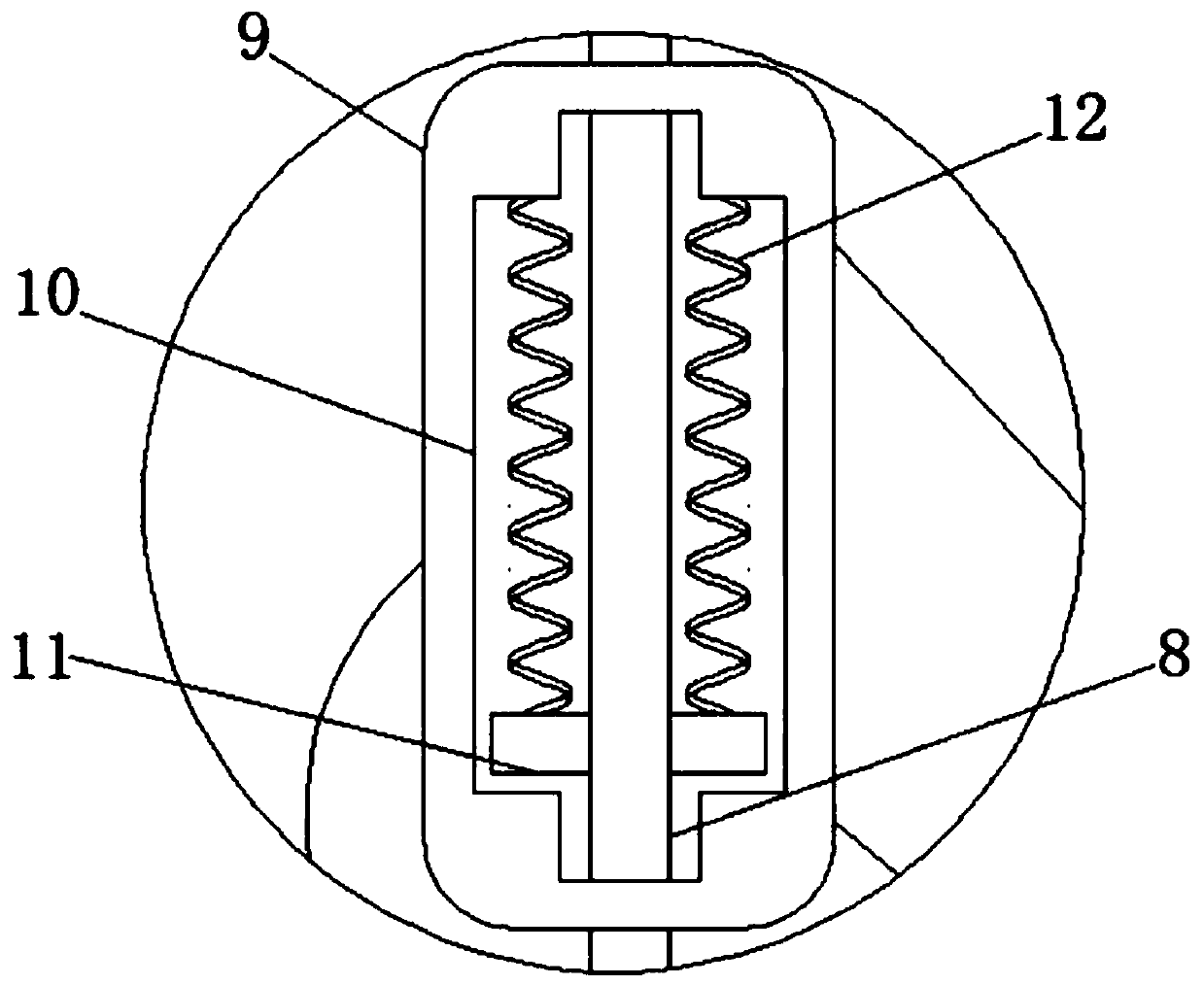
[0017] see Figure 1-3 , the present invention provides a technical solution: a shock-absorbing steel bar cutting device for construction engineering, including a cutting machine body 1, the front and back of the bottom of the cutting machine body 1 are movably connected with a support block 3 through an insertion rod 2, and by setting the insertion Rod 2, so that the insertion rod 2 plays the role of movably connecting the cutting machine body 1 and the suppo...


PUM


Abstract

The invention discloses a damping steel bar cutting device used for constructional engineering. The damping steel bar cutting device comprises a cutting machine body. The front face and the back faceof the bottom of the cutting machine body are movably connected with supporting blocks through insertion rods. The bottoms of the supporting blocks are fixedly connected with bottom plates. Fixing clamping blocks are welded to the left sides of the tops of the bottom plates, and limiting grooves are formed in the left sides and the right sides of the tops of the fixing clamping blocks. Movable clamping blocks are movably connected in inner cavities of the limiting grooves. Pull rods are fixedly connected to the tops of the movable clamping blocks, and the upper portions of the outer sides of the pull rods are sleeved with pressure chambers. Through grooves are formed in the pressure chambers, and sliding blocks are movably connected to the two sides of inner cavities of the through grooves. The tops of the sliding blocks are fixedly connected with springs, and the tops of the pull rods penetrate the pressure chambers and are fixedly connected with handles. Rubber pads are arranged below the bottom plates, and an illumination lamp is arranged at the front end of each bottom plate. By means of the damping steel bar cutting device used for constructional engineering, the function of fixing steel bars conveniently is achieved, and meanwhile the damping function and the night work facilitating function are achieved.

Description

technical field [0001] The invention relates to the technical field of construction engineering equipment, in particular to a shock-absorbing steel bar cutting device for construction engineering. Background technique [0002] Numerous building materials are used in construction projects, and the materials are different. No matter how the society progresses, the status of steel bars in construction projects is irreplaceable. Steel bars are the most used building materials in construction projects. In order to improve the construction The seismic performance of objects, the vast majority of buildings in the construction process, all adopt frame structure, and one of the indispensable materials when building the building frame and steel bars, usually in the specific construction process, workers often according to the construction Rebars are cut using rebar cutting equipment. [0003] In many existing steel bar cutting equipment, in order to facilitate the construction effici...

Claims


Application Information

Patent Timeline
Patent Type & Authority Applications(China)
IPC IPC(8): B21F11/00
CPCB21F11/00
Inventor 方恒
Owner 湖北恩众建筑工程有限公司
Why Eureka
Try Eureka