Linear rotation permanent magnet actuator adopting staggered pole structure

An actuator and linear technology, applied in the direction of electric components, electrical components, electromechanical devices, etc., can solve the problems of increasing production costs, unfavorable promotion and application of permanent magnet actuators, and large amount of permanent magnets, so as to save consumption and structure Simple, loss-reducing effect

Inactive Publication Date: 2015-08-19
SOUTHEAST UNIV
View PDF9 Cites 24 Cited by
  • Summary
  • Abstract
  • Description
  • Claims
  • Application Information

AI Technical Summary

Problems solved by technology

[0004] Existing permanent magnet actuators generally use a large amount of permanent magnets, which significantly increases the production cost, which is not conducive to the popularization and application of this type of permanent magnet actuators

Method used


Image

  • Linear rotation permanent magnet actuator adopting staggered pole structure
  • Linear rotation permanent magnet actuator adopting staggered pole structure
  • Linear rotation permanent magnet actuator adopting staggered pole structure

Examples


Embodiment Construction

[0022] The present invention will be further described below in conjunction with the accompanying drawings.

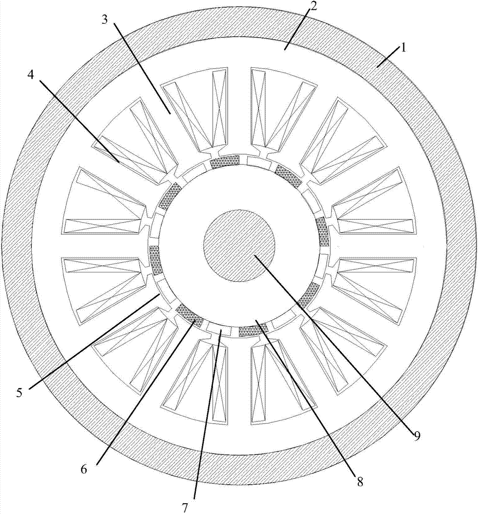
[0023] A linear rotary permanent magnet actuator with staggered pole structure, such as figure 1 As shown, it includes a casing 1, a stator, a mover and a rotating shaft 9, the stator is installed on the casing 1, the mover is installed on the rotating shaft 9, and the mover is arranged in the stator, and the rotating shaft 9 passes through the The sleeve is connected with the casing.

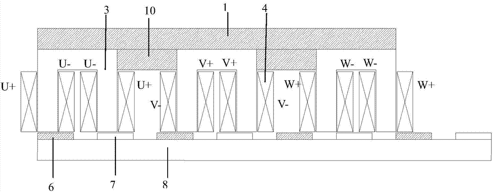
[0024] Such as figure 2 As shown, the stator adopts a 12-tooth structure in the circumferential direction, and the angle between adjacent stator teeth is 30°; three sets of stator units are arranged in the axial direction, and the stator units include the stator yoke 1, the stator pole 4 and the The coil 2 on the iron core has 12 stator poles in the circumferential direction of the stator unit, and the three sets of stator units are connected by non-magnetic connectors 10; the stator...


PUM


Abstract

The invention discloses a linear rotation permanent magnet actuator adopting a staggered pole structure. the linear rotation permanent magnet actuator comprises a housing (1), a stator, a rotor and a rotating shaft (9), wherein the stator is provided with three groups of stator units in the axial direction, the three groups of stator units are connected by virtue of non-magnetic-conducting connectors (10); the stator is provided with first magnetic poles (6) and second magnetic poles (7) which are alternatively arranged in the axial direction, the first magnetic poles (6) comprise first permanent magnetic poles (61) and first iron poles (62) which are alternatively arranged in the circumferential direction, the second magnetic poles (7) comprise second permanent magnetic poles (71) and second iron poles (72) which are alternatively arranged in the circumferential direction, and the first permanent magnetic poles (61) and the second permanent magnetic poles (71) are opposite in magnetism. According to the linear rotation permanent magnet actuator, the consumption of a permanent magnet is greatly reduced, the size of the actuator is reduced, and the power density is increased.

Description

technical field [0001] The invention relates to a high-performance, high-power-density linear rotary permanent magnet actuator capable of realizing linear, rotary and helical compound motions, belonging to the field of motors. Background technique [0002] With the rapid development of industrialization, higher requirements are put forward for the response speed and positioning accuracy of various motion systems. The characteristics of high performance, high power density, small size and smooth motion of actuators have attracted extensive attention. According to the literature, the existing linear rotary actuators are mostly composed of linear motors and rotary motors, which have disadvantages such as complex structures and poor control accuracy. [0003] The patent "linear-rotary motion drive mechanism (CN104019202)" separates the linear and rotary motion drive mechanisms, and uses various mechanical devices to provide conversion between linear and rotary motion. The obviou...

Claims


Application Information

Patent Timeline
Patent Type & Authority Applications(China)
IPC IPC(8): H02K41/03
Inventor 房淑华郭凯凯林鹤云阳辉
Owner SOUTHEAST UNIV
Why Eureka
Try Eureka