
Oil reservoir three-dimensional gas injection method and well pattern structure

A technology of gas injection wells and network structure, which is applied in the fields of fluid production, earth-moving drilling, wellbore/well components, etc., can solve the problem that thick oil reservoirs cannot replenish oil reservoir energy well, and can not well suppress bottom water coning , gas injection mode and insufficient recovery effect, etc., to achieve the effect of improving development effect, increasing microscopic sweep coefficient, and increasing oil production rate and recovery factor

Active Publication Date: 2016-02-03
PETROCHINA CO LTD
View PDF6 Cites 7 Cited by
  • Summary
  • Abstract
  • Description
  • Claims
  • Application Information

AI Technical Summary

Problems solved by technology

Therefore, gas injection in fractured reservoirs is more prone to channeling than water injection, and gas injection in fractured reservoirs is not feasible
Through literature research, some existing gas injection technologies for dual-media reservoirs at home and abroad are limited to gas injection at the top of the reservoir, and the gas injection well must be located in the upper part of the production well for gas injection, which cannot well supplement the middle and lower parts of the reservoir for thick reservoirs The energy of the bottom water cannot be suppressed very well.
[0005] In summary, the existing gas injection methods have shortcomings in gas injection methods and production effects. Therefore, providing an effective reservoir gas injection method and well pattern structure has become an urgent problem to be solved in this field.

Method used


Image

  • Oil reservoir three-dimensional gas injection method and well pattern structure
  • Oil reservoir three-dimensional gas injection method and well pattern structure
  • Oil reservoir three-dimensional gas injection method and well pattern structure

Examples


Embodiment 1

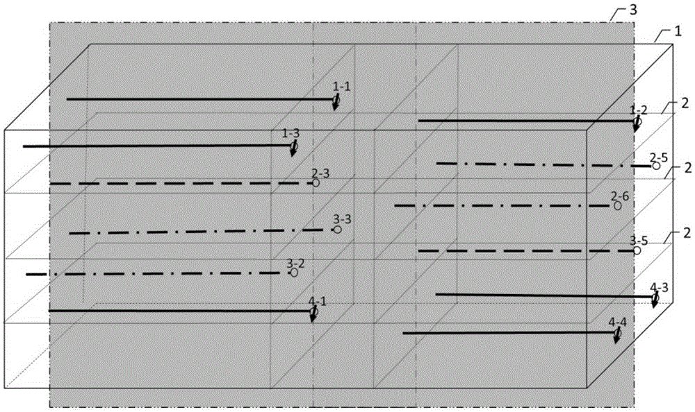
[0044] This embodiment provides a three-dimensional gas injection method and a well pattern structure for a reservoir. The Xinggu Block 7 in the Xinggu buried hill oil reservoir of the Liaohe Oilfield was carried out. The reservoir is ancient, complex in structure and diverse in lithology. It is a buried-hill reservoir of fractured massive bottom-water metamorphic rock with extremely thick reservoirs. The area of ​​the experimental area is 9.77km 2 , reservoir thickness 2335m, geological reserves 3537×10 4 t, matrix reserves accounted for 65%, macro fracture reserves accounted for 12%, micro fracture reserves accounted for 23%, reservoir matrix permeability was 0.47mD, fracture permeability was 140mD, formation crude oil viscosity was 0.527MPa·s.

[0045] A three-dimensional injection-production well pattern with four sections and seven layers vertically stacked and staggered is selected and formed with a horizontal injection-production well spacing of 300m and a vertical le...


PUM


Abstract

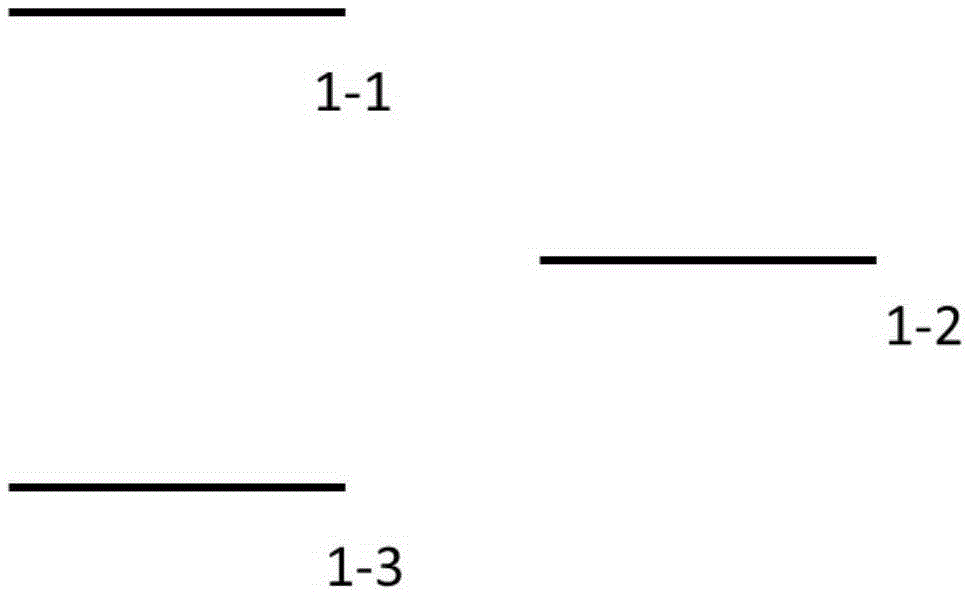
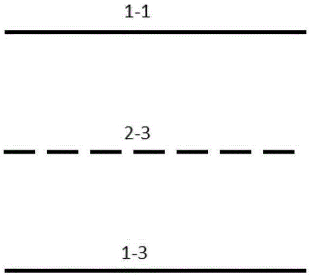
The invention provides an oil reservoir three-dimensional gas injection method and a well pattern structure. The oil reservoir three-dimensional gas injection method comprises steps of simultaneously injecting gas to the top portion and the lower portion of an oil reservoir, wherein gas-injection wells for the lower portion of the oil reservoir are a part of watered-out wells which are arranged at the lower portion of the oil reservoir 1-2 years ago before gas injection. The invention also provides the oil reservoir three-dimensional gas injection well pattern structure comprising multiple horizontal production wells and multiple horizontal gas injection wells. The horizontal wells in adjacent rows in the same plane are arranged in a staggered manner, and the horizontal wells in the adjacent layers in the vertical view are also arranged in a staggered manner, so that the three-dimensional gas injection well pattern structure in which the horizontal wells are arranged in a staggered manner in the plane and vertical views is formed. The oil reservoir three-dimensional gas injection method and the well pattern structure can effectively improve the oil extraction efficiency.

Description

technical field [0001] The invention relates to an oil reservoir gas injection method, in particular to an oil reservoir three-dimensional gas injection method and a well pattern structure, and belongs to the technical field of oil reservoir exploitation. Background technique [0002] For dual-media reservoirs, the permeability of the reservoir matrix is ​​too small and the permeability of fractures is high. In the process of natural energy extraction, the oil wells have high production at the initial stage of production, and the production basically comes from fractures; as production progresses, the supply capacity of fractures The crude oil in the matrix system begins to flow into the fractures. Due to the low flow coefficient of the matrix and the slow oil supply rate, it cannot make up for the decline in the oil supply capacity of the fracture system, so the oil well production declines rapidly; with the rapid coning of the bottom water along the fractures, the oil The ...

Claims


Application Information

Patent Timeline
IPC IPC(8): E21B43/16E21B43/30
Inventor 任芳祥张方礼龚姚进许宁邱林徐萍周万山徐明旺司勇梁飞陈东明李若懿王刚王尚慧邢淑霞
Owner PETROCHINA CO LTD
Learn More