This helps you quickly interpret patents by identifying the three key elements:
Problems solved by technology
Method used
Benefits of technology
[0096] In another aspect, the present invention provides a photocurable composition comprising (a) a first photopolymer mixture, which on polymerization induces an immediate increase in viscosity and (b) a second photopolymer mixture, which is slower reacting than (a), and results in less shrinkage and higher Tg cured properties compared to the first mixture.
[0097] In another aspect, the present invention provides a photocurable composition comprising (a) a first photopolymer mixture, which on polymerization induces an immediate increase in viscosity and (b) a second photopolymer mixture which is slower reacting, and results in less shrinkage and higher Tg cured properties compared to the first mixture, such that the ultim
Problems solved by technology
All these material-machine systems have limitations in one area or another, which limit direct usefulness of the finally formed three-dimensional article.
All of these systems also have limitations for speed of access to the formed three-dimensional articles: especially from those, which use laser scanning exposure processes.
In the past, articles produced by rapid prototyping were initially so brittle that increasing brittleness associated with aging went unnoticed.
Other radiation sources, which produce non-coherent radiation, cannot achieve the same curing speeds as laser radiation and require the use of much faster-curing compositions to provide sufficient green strength to enable the a
Method used
Image
Click on the blue label to locate the original text in one second.
Reading with bidirectional positioning of images and text.
Examples
examples
1) Acrylic Composition
[0179] Stereolitiography Resin SL5131, an acrylic formulation, from Huntsman Advanced Materials, was imaged in an SL7000 machine and also according to the method of WO 00 / 21735.
[0180] Results are presented below, clearly showing improvement in Tensile Stress values:
SystemWO 00 / 21735SLA7000Tensile stress (MPa)6240Elongation at break (%)3.32-3Tensile modulus (MPa)2210N / A
2) Acrylic-Polythiol Composition 1
[0181] The following compounds were mixed at room temperature for 2 hours, under yellow light, in a brown bottle.
[0182] Ebecryl 8402 is an urethane diacrylate component which has, according to US 20040181007, a Mw of 1000.
[0183] The composition was imaged in an SL7000 machine and also according to the method of WO 00 / 2...
examples 4 to 8
[0189] The following formulations were made by tumble mixing the components [wt %] in a brown jar, having tightly sealing cap: room temperature for 6 hours.
[0190] Viscosity of fluids was measured using a Brookfield HBTD Viscometer (0.8° cone spindle) at both 25° C.
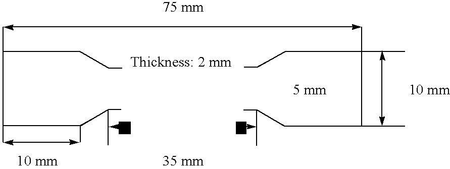
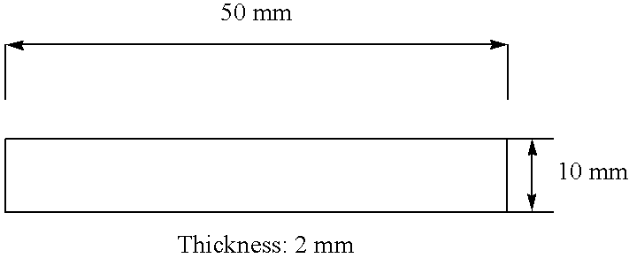
[0191] Mould Cured Samples: the formulations were poured into a silicone mould and cured under UV (Fusion Systems F450 lamp, 120 W / cm2, 7.5 s). The parts were removed from the mould, turned, and cured under UV again (Fusion SystemsF450 lamp, 120 W / cm2, 7.5 s). Tensile properties were measured using Stable Micro Systems TA-HDi Texture Analyser, test speed 0.08 mm / s, grip distance 55 mm.
PUM
Property
Measurement
Unit
Fraction
aaaaa
aaaaa
Time
aaaaa
aaaaa
Time
aaaaa
aaaaa
Abstract
An optical moulding process is disclosed comprising the sequential steps of: (a)(y) forming a layer of a photocurable composition; and (bXz) irradiating selected areas of the composition in the layer with radiation from a radiation source, thereby curing the composition in said selected areas and repeating the steps a) and b) on top of an earlier cured layer to form a three dimensional structure, wherein the radiation source used in step b) is a non-coherent source of radiation and wherein the photocurable composition comprises at least two curable components: (i) 45%-95% (and preferably at least 50%, more preferably at least 60%, e.g. at least 70%) by weight of the total curable components in the composition is a first component that is photocurable and that is such that, when cured in the presence of a photocuring initiator by exposure to UV radiation having an energy of 30 mJ/cm2, at least 90% of the component is cured within 50 milliseconds; and (ii) 5% to 55% (and preferably 10-40%, more preferably 15 to 30%, e.g. about 20%) by weight of the total curable components in the composition is a second component that results in the composition, on curing, shrinking, in a linear direction, by less than 3% and preferably that results in the composition having, after cure, a Tg of greater than 50° C., preferably at least 100° C. and more preferably at least 120° C.
Description
FIELD OF THE INVENTION [0001] The present invention relates to photocurable compositions and processes for producing three-dimensional articles using rapid prototyping techniques. Three-dimensional articles produced from the photocurable compositions of the present invention exhibit overall high performance properties. BACKGROUND OF THE INVENTION [0002] Three-dimensional articles produced from CAD using layerwise rapid prototyping techniques (e.g. stereolithography) have been available for a number of years. The ultimate mechanical and other [e.g. surface finish etc] properties of such articles are derived from the materials and the CAD layering system being used. [0003] For example, stereolithography systems, e.g. as described in U.S. Pat. No. 4,575,330, utilize complex photopolymer mixtures addressed by UV lasers to produce the 3 D articles. The polymer mixtures used in such machines have progressed from initial acrylic systems [e.g. U.S. Pat. No. 6,043,323], suitable for concept ...
Claims
Application Information
Patent Timeline
Application Date:The date an application was filed.
Publication Date:The date a patent or application was officially published.
First Publication Date:The earliest publication date of a patent with the same application number.
Issue Date:Publication date of the patent grant document.
PCT Entry Date:The Entry date of PCT National Phase.
Estimated Expiry Date:The statutory expiry date of a patent right according to the Patent Law, and it is the longest term of protection that the patent right can achieve without the termination of the patent right due to other reasons(Term extension factor has been taken into account ).
Invalid Date:Actual expiry date is based on effective date or publication date of legal transaction data of invalid patent.