A permanent magnet differential transmission mechanism

A differential transmission and permanent magnet technology, applied in the field of transmission mechanism and permanent magnet differential transmission mechanism, can solve the problems of being unsuitable for large-scale use, unable to change the transmission ratio, and high technical requirements, reducing the moving distance and saving permanent magnets , the effect of improving transmission efficiency

Inactive Publication Date: 2017-06-20
NANJING INST OF TECH
View PDF8 Cites 0 Cited by
  • Summary
  • Abstract
  • Description
  • Claims
  • Application Information

AI Technical Summary

Problems solved by technology

[0003] For a relatively complete transmission device, there is a hydraulic torque converter, but its structure is complicated, its technical requirements are high, its production cost is high, and it is not suitable for large-scale use; and although the permanent magnet coupling is simple in structure and high in transmission efficiency, it has not been developed so far. It is impossible to change its transmission ratio; as for the permanent magnet eddy current technology, although it can realize stepless speed change, it is relatively too large and too complicated to install

Method used


Image

  • A permanent magnet differential transmission mechanism
  • A permanent magnet differential transmission mechanism
  • A permanent magnet differential transmission mechanism

Examples


Embodiment Construction

[0028] Below in conjunction with accompanying drawing of description, the present invention will be further described.

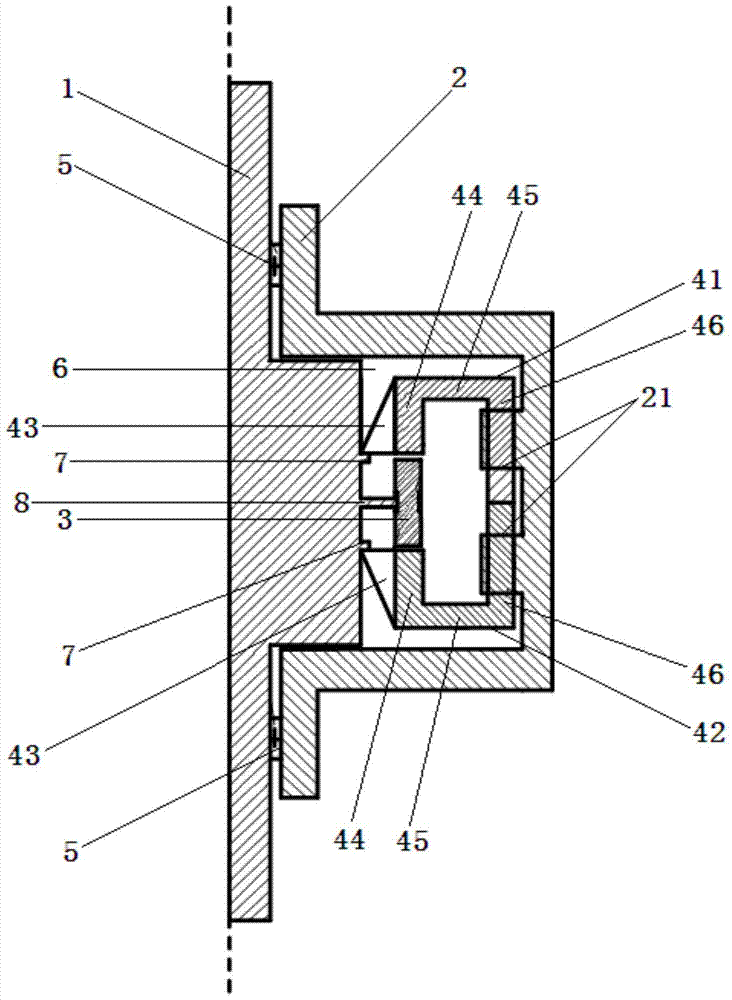
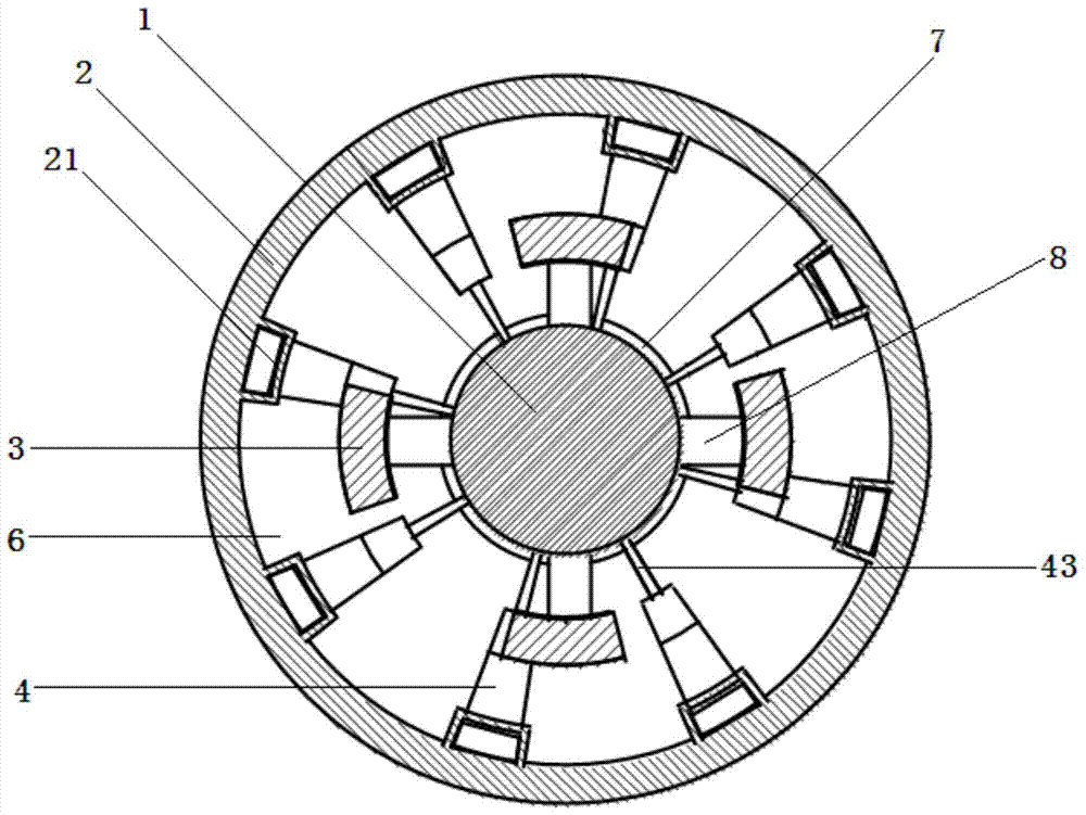
[0029] Such as figure 1 and figure 2 As shown, a permanent magnet differential transmission mechanism includes an inner shaft 1, an outer shaft 2, a permanent magnet rotor 3 and a magnetically permeable rotor 4. The magnetically permeable rotor 4 includes a first ferromagnetic block 41 and a second ferromagnetic block 41 arranged symmetrically. Two ferromagnetic blocks 42.

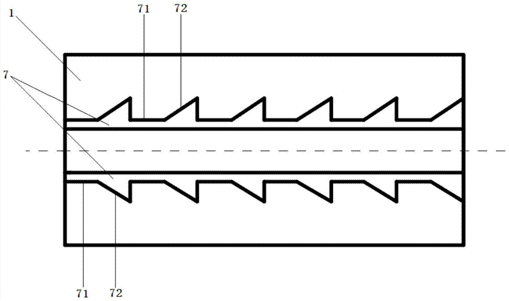
[0030] The inner shaft 1 is connected to the outer shaft 2 through a bearing 5, and an accommodating cavity 6 is provided between the inner shaft 1 and the outer shaft 2 for accommodating the permanent magnet rotor 3 and the magnetic permeable rotor 4; the permanent magnet rotor The quantity ratio of 3 and magnetic permeable rotor 4 is 1:2, and they are evenly spaced; the inner shaft 1 is connected to the permanent magnet rotor 3, and the circumferential surface of the inner shaft 1 i...


PUM


Abstract

The invention discloses a permanent magnet differential transmission mechanism, which comprises an inner shaft, an outer shaft, a permanent magnet rotor and a magnetically permeable rotor. The magnetically permeable rotor includes a first ferromagnetic block and a second ferromagnetic block arranged in pairs; The shaft is connected to the outer shaft through bearings, and the inner shaft is connected to the permanent magnet rotor. Two rows of convex grooves are arranged on the circumferential surface of the inner shaft, and the permanent magnet rotor is distributed between the two rows of convex grooves; the ratio of the number of permanent magnet rotors to magnetically conductive rotors 1:2, evenly spaced; one end of the first ferromagnetic block and the second ferromagnetic block are connected to the outer shaft through the sliding groove, and the other end is respectively in contact with the two rows of convex grooves of the inner shaft through the connecting plate. As the inner shaft rotates, after the connecting plate slides along the protruding groove, along the groove track of the sliding groove, switching is performed between facing away from each other and relatively close to closing. Through the change of the magnetic circuit, the positive output torque can still be maintained under the condition of differential speed, the volume is reduced, the structure is simplified, and the energy lost in sliding friction can be reduced at the same time, and the transmission efficiency can be improved.

Description

technical field [0001] The invention relates to a transmission mechanism, in particular to a permanent magnet differential transmission mechanism, which belongs to the technical field of mechanical transmission equipment. Background technique [0002] With the development of human society, we are more and more inseparable from power, and various transmission devices are developing rapidly; however, various continuously variable transmission devices therein also have their own shortcomings. [0003] For a relatively complete transmission device, there is a hydraulic torque converter, but its structure is complicated, its technical requirements are high, its production cost is high, and it is not suitable for large-scale use; and although the permanent magnet coupling is simple in structure and high in transmission efficiency, it has not been developed so far. It is impossible to change its transmission ratio; as for the permanent magnet eddy current technology, although it ca...

Claims


Application Information

Patent Timeline
Patent Type & Authority Patents(China)
IPC IPC(8): H02K51/00
Inventor 盛愈欢邹伟汤路林驰皓邹政耀
Owner NANJING INST OF TECH
Why Eureka
Try Eureka