
System and method for detecting ONT abnormal luminescence with OLT in PON system

A technology of abnormal light emission and detection instruction, applied in the field of optical network communication, can solve the problem of inability to detect ONT time slot occupancy, the allocation of EPONONT time slot length is not fixed, and the inability to accurately detect ONT optical link status, etc. hidden effect

Inactive Publication Date: 2015-08-19
PHICOMM (SHANGHAI) CO LTD
View PDF5 Cites 1 Cited by
  • Summary
  • Abstract
  • Description
  • Claims
  • Application Information

AI Technical Summary

Problems solved by technology

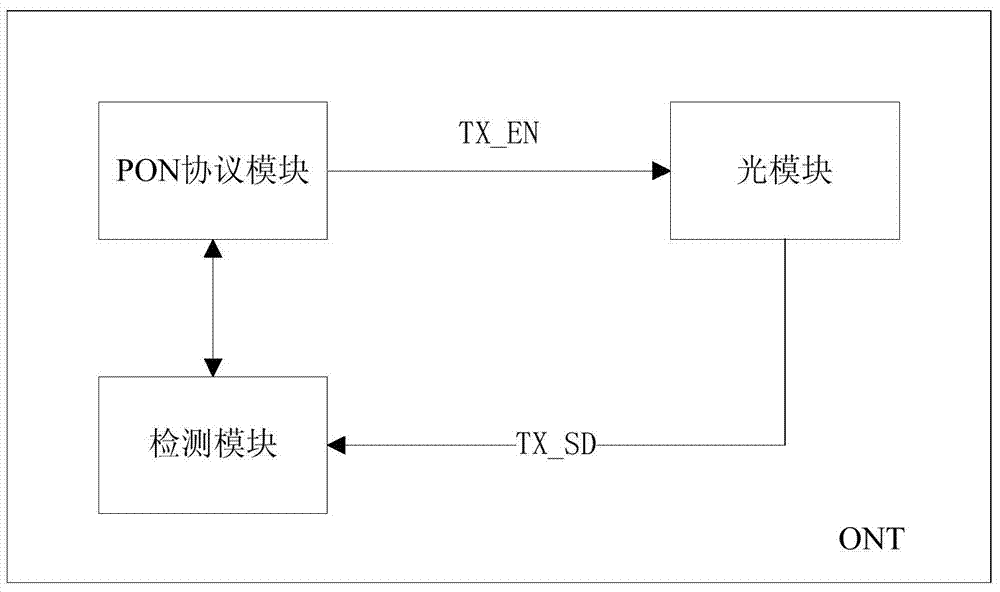
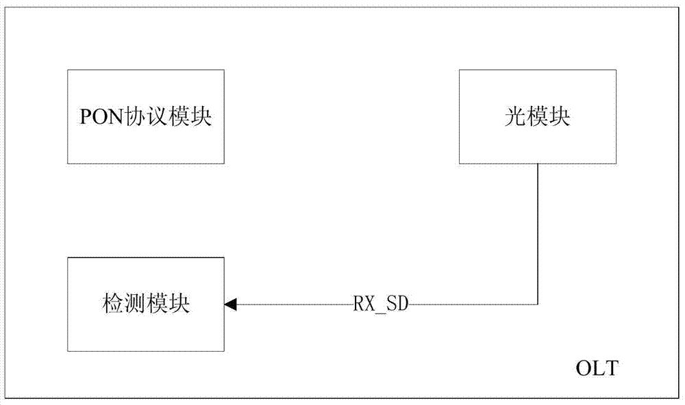
Although this solution can detect link failures caused by ONT abnormal light emission, due to the unfixed allocation of EPON ONT uplink time slot lengths, there is no way to detect time slot occupancy problems caused by ONT optical device aging, and it is also impossible to accurately detect each ONT Uplink optical link status

Method used


Image

  • System and method for detecting ONT abnormal luminescence with OLT in PON system
  • System and method for detecting ONT abnormal luminescence with OLT in PON system
  • System and method for detecting ONT abnormal luminescence with OLT in PON system

Examples


Embodiment Construction

[0044] Embodiments of the present invention are described below through specific examples, and those skilled in the art can easily understand other advantages and effects of the present invention from the content disclosed in this specification. The present invention can also be implemented or applied through other different specific implementation modes, and various modifications or changes can be made to the details in this specification based on different viewpoints and applications without departing from the spirit of the present invention.

[0045] It should be noted that the diagrams provided in this embodiment are only schematically illustrating the basic idea of ​​the present invention, and only the components related to the present invention are shown in the diagrams rather than the number, shape and shape of the components in actual implementation. Dimensional drawing, the type, quantity and proportion of each component can be changed arbitrarily during actual impleme...


PUM


Abstract

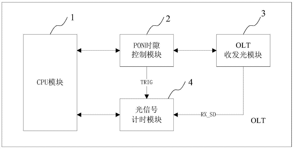
The invention provides a system and a method for detecting ONT abnormal luminescence with an OLT in a PON system. The system comprises a CPU module, a PON time slot control module, an OLT light receiving and transmitting module and an optical signal timing module; the OLT light receiving and transmitting module is connected with the PON time slot control module, and the PON time slot control module is connected with the optical signal timing module and the CPU module, and the optical signal timing module is connected with the CPU module. The system and the method for detecting ONT abnormal luminescence with the OLT in the PON system of the invention can be used for accurately detecting state of each ONT uplink data, detecting performance deterioration condition of single ONT, fast locating degradation fault point so as to be convenient for removing hidden danger before further deterioration.

Description

technical field [0001] The present invention relates to the technical field of optical network communication, in particular to an optical line terminal (Optical Line Terminal, OLT) detection of an optical network terminal (Optical network terminal, ONT) abnormality in a passive optical network (Passive Optical Network, PON) system Light emitting systems and methods. Background technique [0002] At present, the PON optical network has been widely used in the access network. Its network topology is that one OLT port is connected to multiple ONT devices, and the downlink data is broadcast by the OLT to all ONTs. Multiple ONT devices send uplink data on the same wavelength through time-division multiplexing, and the allocation of uplink time slots is determined by the OLT. Therefore, the network topology of the PON is a point-to-multipoint master-slave communication mechanism, and the OLT precisely controls the start time and end time of sending uplink data of each ONT device....

Claims


Application Information

Patent Timeline
Patent Type & Authority Applications(China)
IPC IPC(8): H04B10/075
CPCH04B10/075
Inventor 吴夕周杨传培
Owner PHICOMM (SHANGHAI) CO LTD
Learn More