Mobile terminal
A technology of mobile terminals and back shells, which is applied in the field of mobile terminals, can solve the problems of increased size, increased width of the whole machine, and easy pressing, so as to achieve the reduction of the thickness of the whole product, ensure the reliability of the connection, and reduce the overall size of the product. effect of thickness
- Summary
- Abstract
- Description
- Claims
- Application Information
AI Technical Summary
Problems solved by technology
Method used
Image

Examples
Embodiment 1
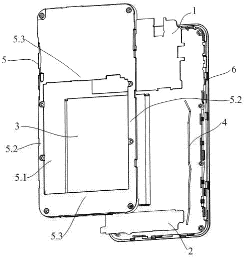
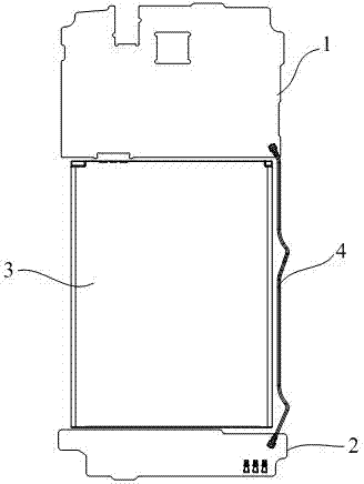
[0034] refer to Figure 4 to Figure 6 , the mobile phone product of this embodiment includes a back shell and a front shell 2, wherein the back shell adopts a broken plate design, and includes an upper back shell 6 and a lower back shell 7 separated from each other, and the upper back shell 6 and the lower back shell 7 still use screws and The front shell 2 is connected, and the battery placement area 11 is between the upper back shell 6 and the lower back shell 7. The side of the front shell 2 facing the back shell is provided with a limiting structure. When the battery 1 is placed in the battery placement area 11, the battery 1 It is located between the upper back shell 6 and the lower back shell 7, and the limiting structure is used to limit it.
[0035] Using the split-plate mobile phone in this embodiment, the mobile phone back shell is divided into two parts, the upper back shell and the lower back shell. On the basis of ensuring the strength, the thickness is further r...
Embodiment 2
[0046] refer to Figure 7 to Figure 9 , the difference from Embodiment 1 is that in this embodiment, a limit block 2.5 is fixed at the notch of the accommodation groove 2.3 to limit the front and rear direction of the protective cover 8, and one end of the second rib 2.2 is set There is a stop block 2.6 for limiting one end of the protective cover 8, and the other end of the protective cover 8 is limited by the lower back shell 7 or the upper back shell 6 at this end. For ease of description, in this embodiment, a stop block 2.6 is provided on the upper end of the second rib 2.2 to limit the upper end of the protective cover 8 , and the lower end of the protective cover 8 is limited by the lower back shell 7 . During installation, the protective cover 8 is inserted from the lower end of the second convex rib 2.2 without a stopper until the upper end of the protective cover 8 is blocked by the stopper 2.6, that is, plugged into place, and then the lower back shell 7 is installe...
Embodiment 3
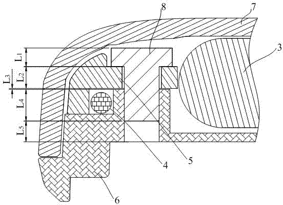
[0049] refer to Figure 10 and Figure 11 In this embodiment, the protective cover 8 is a T-shaped strip cover, which is fastened on the second rib 2.2, and the protective cover 8 is bonded to the second rib 2.2, and the two ends of the second rib 2.2 are provided with There is a stop block 2.7 to limit the up and down direction of the protective cover 8, and the protective cover 8 is positioned to prevent up and down movement. In this embodiment, the installation structure of the protection cover 8 is simple, the installation efficiency is high, and the installation order of the protection cover 8 and the upper back shell 6 and the lower back shell 7 does not affect each other, and the installation is flexible.
PUM
 Abstract
Description
Claims
Application Information
 - R&D
- Intellectual Property
- Life Sciences
- Materials
- Tech Scout
- Unparalleled Data Quality
- Higher Quality Content
- 60% Fewer Hallucinations
Browse by: Latest US Patents, China's latest patents, Technical Efficacy Thesaurus, Application Domain, Technology Topic, Popular Technical Reports.
© 2025 PatSnap. All rights reserved.Legal|Privacy policy|Modern Slavery Act Transparency Statement|Sitemap|About US| Contact US: help@patsnap.com