A high-efficiency power generation shoe

A power generation shoe, high-efficiency technology, applied in the direction of shoe soles, footwear, electromechanical devices, etc., can solve the problems of low power generation efficiency and uncomfortable wearing, and achieve the effect of improving efficiency and stabilizing air pressure

Active Publication Date: 2017-02-22
上海霍雷加新材料科技有限公司
View PDF1 Cites 0 Cited by
  • Summary
  • Abstract
  • Description
  • Claims
  • Application Information

AI Technical Summary

Problems solved by technology

[0004] The technical problem to be solved by the present invention: Aiming at the problems of low power generation efficiency and uncomfortable wearing in the existing power generation shoes, a high-efficiency power generation shoe is now provided. When the shoes are on the ground, they have stable power output, and when the shoes are off the ground, they can still continue to generate electricity

Method used


Image

  • A high-efficiency power generation shoe
  • A high-efficiency power generation shoe
  • A high-efficiency power generation shoe

Examples


Embodiment 1

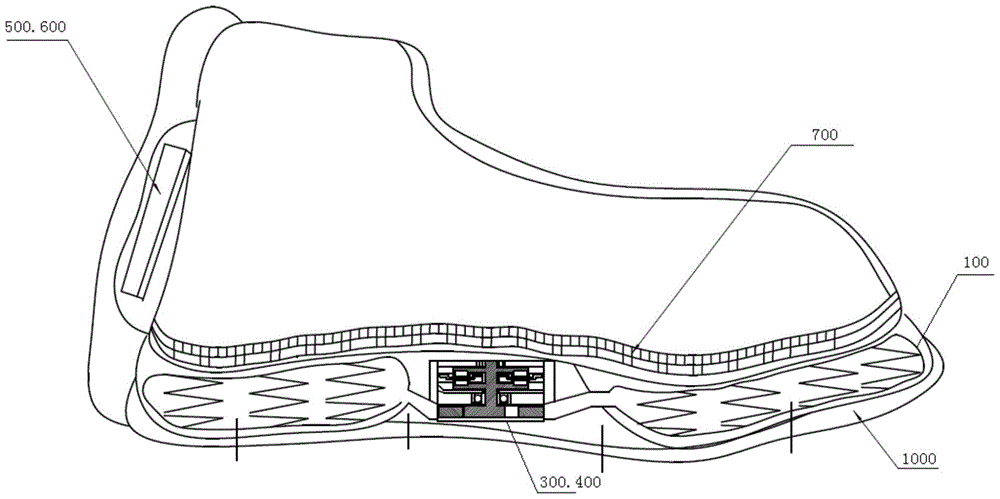
[0053] see Figure 1 to Figure 3 , the figure shows a high-efficiency power generation shoe, including at least one cavity 100 , a gas accumulator 200 , an airflow-driven power generation device and an energy storage device 500 .

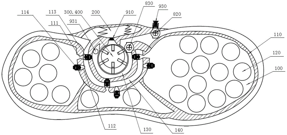
[0054] The cavity 100 is arranged in the sole, can be compressed and recovers its deformation by its own elasticity after compression. In this embodiment, there are three cavities 100, which are respectively located at the forefoot, heel and sole of the sole, and are basically all over the sole. No matter how the power generation shoe lands, the cavities 100 will be compressed.

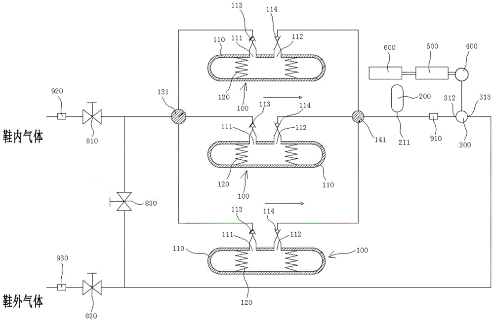
[0055] Each cavity 100 is composed of an air bag 110 and an elastic element 120 arranged in the air bag 110 to restore the deformation of the air bag 110. An air inlet 111 and an air outlet 112 are provided on the air bag 110. There is a check valve 113, so that the air inlet 111 can only take in air but not air out, and a check valve 114 is installed on the air outlet 112...

Embodiment 2

[0079] see Figure 17 and Figure 18 , the structure of this embodiment is substantially the same as that of Embodiment 1, the difference is that the installation positions of the air motor 300a and the permanent magnet direct drive generator 400a are different, and the installation positions of the second regulating valve 820a and the third regulating valve 830a Are not the same. In this embodiment, the air motor 300a and the permanent magnet direct drive generator 400a are installed on the inner side of the foot of the shoe body, and the first and third filter valves 910a, 930a, the second regulating valve 820a and the third regulating valve 830a are also installed Installed on the inner side of the foot of the shoe body.


PUM


Abstract

The invention discloses an efficient generating shoe capable of generating electricity. The efficient generating shoe comprises at least one cavity formed in the sole of the shoe, an airflow-driven generating device, an energy accumulator connected with the airflow-driven generating device through a control circuit and an air energy accumulator for storing pressure air, wherein the cavities can be compressed and can restore deformation on the dependence of the elasticity of the cavities. Each cavity is provided with a one-way air inlet and a one-way air outlet. All the one-way air inlets gather to form a main one-way air inlet. All the one-way air outlets gather to form a main one-way air outlet. The airflow-driven generating device is provided with an air inlet and an air outlet which are connected with the main one-way air outlet. The air energy accumulator for storing pressure air is arranged between the air inlet and the main one-way air outlet of the airflow-driven generating device. When the shoe gets away from the ground, the air energy accumulator can supply air to the airflow-driven generating device continuously till the pressure of the air inlet and the pressure of the air outlet of the airflow-driven generating device reaches the balance, and the generating efficiency is improved effectively.

Description

technical field [0001] The invention relates to a high-efficiency power generation shoe, which converts part of the mechanical energy of the human body into the potential energy of the elastic element and the static pressure energy and kinetic energy of the gas, wherein the potential energy of the elastic element is used to suck the external gas into the shoe, and the gas The static pressure energy and kinetic energy of the air motor are used to drive the air motor to rotate, and the mechanical energy is converted into electrical energy through the direct drive permanent magnet generator, and then the electrical energy is stored in the storage battery through the control circuit. Background technique [0002] The Chinese patent No. 200720111329.0 discloses a multifunctional power generation shoe, see Figure 19 , which includes the sole and the upper, the sole 1 is provided with an elastic airbag 3, the elastic airbag 3 has a one-way air inlet 4 and a one-way air outlet 5, an...

Claims


Application Information

Patent Timeline
Patent Type & Authority Patents(China)
IPC IPC(8): A43B13/20A43B13/22A43B7/32A43B7/06F01D15/10H02K7/18
Inventor 王江涛王亮
Owner 上海霍雷加新材料科技有限公司
Why Eureka
Try Eureka