
737ng series aircraft main landing gear axle sleeve and brake sleeve removal tooling

A 737NG, disassembly tooling technology, used in aircraft parts, metal processing, manufacturing tools, etc., can solve problems such as large diameter differences, tool and component damage, and difficulty in removal, to speed up disassembly, improve work efficiency, and shorten maintenance. effect of cycles

Active Publication Date: 2017-03-01
SHANDONG TAIKOO AIRCRAFT ENG
View PDF10 Cites 0 Cited by
  • Summary
  • Abstract
  • Description
  • Claims
  • Application Information

AI Technical Summary

Problems solved by technology

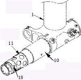
However, during the long-term operation of the aircraft, the main landing gear 1 wheel shaft sleeve and the brake sleeve 10 are subjected to multiple effects of thermal stress due to repeated high-speed braking work, so that they are closely matched with the wheel shaft. For the special tools given in the manual, the strength of the pull rod and the supporting pins generally cannot meet the actual requirements, resulting in the situation that the tool is pulled and damaged from time to time.
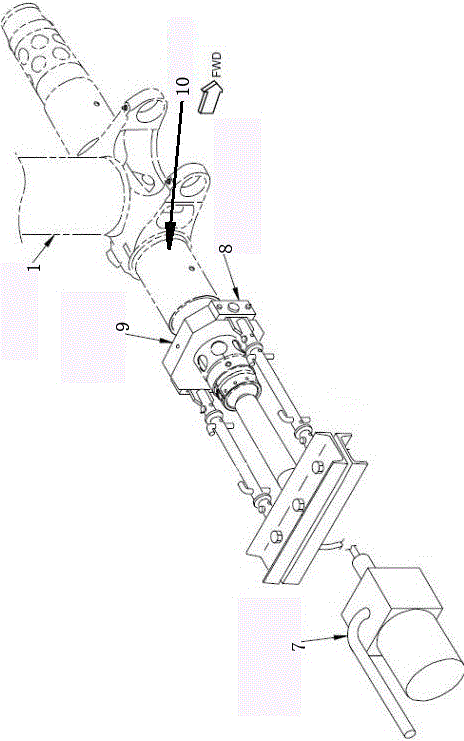
at the same time as figure 2 As shown in , when removing the axle sleeve, it is completed by contacting the wheel axle sleeve removal pull pin on the special tool with the process hole of the axle sleeve to transmit force. The hole diameters are very different, and their actual contact is point contact force transmission, the contact area is small, the stress is large, and tools and components are often damaged under high tension
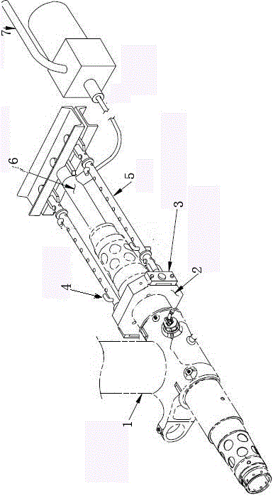
[0003] 737NG series aircraft remove and disassemble the main landing gear axle sleeve and brake sleeve. The usual method is: first use the special tool provided in the manual to remove the brake sleeve. Generally, the tight fit contact area between the brake sleeve and the wheel shaft is small, and the brake sleeve on the brake sleeve is small. The inner diameter of the process hole matches the outer diameter of the brake sleeve removal pull pin assembly 3 installed on the brake sleeve positioning plate 2, and the contact area is relatively large. Using the manual hydraulic pump 7 and hydraulic cylinder 6 together can basically be recommended by the manual. Dismantling is completed with special tools, and for a few that cannot be removed, the method of external heating and expansion can be used to complete the removal of the brake sleeve, but the connecting pin 4 on the tie rod 5 and its mounting hole are easily damaged
[0005] 1) Difficult to remove, low efficiency, prone to component damage and tool damage, affecting the flight cycle of the aircraft, and the destruction and decomposition time exceeds 2 days when encountering difficulties;
[0006] 2) The force contact surface is small, and it is easy to generate derivative risks and cause personal injury under the high pressure of 100000PSI;
[0007] 3) There is a risk of damaging the axle during the process of destroying and removing the axle sleeve. Once the axle is damaged, it may be necessary to order a replacement, but ordering is difficult, which can easily cause delays in the aircraft inspection cycle

Method used


Image

  • 737ng series aircraft main landing gear axle sleeve and brake sleeve removal tooling
  • 737ng series aircraft main landing gear axle sleeve and brake sleeve removal tooling
  • 737ng series aircraft main landing gear axle sleeve and brake sleeve removal tooling

Examples


Embodiment Construction

[0035] combine Figure 3 to Figure 9 , a 737NG series aircraft main landing gear 1 axle sleeve 11 and brake sleeve 10 disassembly tooling,

[0036] Including the brake sleeve positioning plate 2 and the brake sleeve removal pull pin assembly 3 installed on the brake sleeve positioning plate, the pull pin of the brake sleeve removal pull pin assembly is matched with the brake sleeve removal hole;

[0037]It also includes a driving hydraulic cylinder 16, a hydraulic cylinder mount 15 for installing the driving hydraulic cylinder, an aluminum spacer 14 and at least two pull rods 13. The pull rod can be made of high-strength steel, which can withstand 10 grades of tension. Both the brake sleeve positioning plate and the hydraulic cylinder mounting seat have the same number of through holes for the pull rods to pass through. Each pull rod runs through a through hole on the brake sleeve positioning plate and the hydraulic cylinder mounting seat. The nut threaded with the tie rod r...


PUM


Abstract

The invention provides disassembly technological equipment of main undercarriage axle sleeves and brake sleeves of 737NG series aircrafts. The disassembly technological equipment comprises a brake sleeve positioning plate, a brake sleeve-disassembling broaching module, a driving hydraulic cylinder, a hydraulic cylinder mounting base, an aluminous heel block, at least two pull rods and a sleeve body, wherein a broaching is matched with a brake sleeve disassembling hole; the brake sleeve positioning plate and the hydraulic cylinder mounting base are all provided with through holes; each pull rod all penetrates through two through holes; the brake sleeve positioning plate and the hydraulic cylinder mounting base are limited on the pull rods through nuts; the sleeve body comprises a cylinder part and a flange and two half bodies connected face to face. When the equipment is used, the sleeve body sleeves an axle, the flange end of the sleeve body is in contact with the inner end surface of an axle sleeve, the brake sleeve positioning plate sleeves the cylinder part, and the inner diameter of the center hole of the brake sleeve positioning plate is smaller than the outer diameter of the flange; when in disassembly, the hydraulic cylinder mounting base is positioned on the outer side of the outer end of the main undercarriage axle, a position rod presses the aluminous heel block on the outer end of the main undercarriage axle to convey the acting force to the main undercarriage axle through the aluminous heel block.

Description

technical field [0001] The invention relates to the removal and disassembly of the main landing gear hub and brake sleeve of 737NG series aircraft, and specifically relates to the removal tooling for the main landing gear hub and brake sleeve of the 737NG series aircraft. Background technique [0002] When removing and disassembling the main landing gear axle sleeves and brake sleeves of 737NG series aircraft, special tools are given in the relevant Boeing maintenance manuals (such as figure 1 with figure 2 shown). However, during the long-term operation of the aircraft, the main landing gear 1 wheel shaft sleeve and the brake sleeve 10 are subjected to multiple effects of thermal stress due to repeated high-speed braking work, so that they are closely matched with the wheel shaft. For the special tools given in the manual, the strength of the pull rods and the supporting pins generally cannot meet the actual requirements, resulting in the situation that the tools are pul...

Claims


Application Information

Patent Timeline
Patent Type & Authority Patents(China)
IPC IPC(8): B23P19/027
CPCB23P19/025B23P19/027B23P2700/01
Inventor 王创业
Owner SHANDONG TAIKOO AIRCRAFT ENG
Learn More