Screening gravel grab bucket

A gravel and grab technology, which is applied to earth movers/excavators, construction, etc., can solve the problems that affect the strength of buildings, do not have screening or filtering, and grab stones with small volume, so as to improve the grab Efficiency, increased volume, and increased strength

Active Publication Date: 2015-08-26
浙江雅迅眼镜科技有限公司
View PDF5 Cites 15 Cited by
  • Summary
  • Abstract
  • Description
  • Claims
  • Application Information

AI Technical Summary

Problems solved by technology

[0003] With the rise of the real estate industry in recent years, there are more and more high-rise building construction projects. Stones, an indispensable raw material, are used in house construction. Mixing stones and cement together can enhance the strength of buildings. The overall strength, the stones used in construction are first crushed by the stone crusher in the stone factory and then transported to the construction site for use. Because the weight of the stone is heavy, and the shape of the stone is sharp and different in shape, the stone is transported to the transport vehicle. The tool that must be used in the process is the grab bucket. Since the stone will be mixed with sand during the mining and crushing process, if the sand mixed with the stone is not removed, it will directly affect the strength of the building. However, the existing grab The bucket does not have the function of screening or filtering; and when the grab grabs the gravel, because the front end of the grab is fixed and flat, the grab grabs a small volume of gravel at one time, and the grabbing work efficiency is low.

Method used


Image

  • Screening gravel grab bucket
  • Screening gravel grab bucket
  • Screening gravel grab bucket

Examples


Embodiment Construction

[0021] In order to make the technical means, creative features, goals and effects achieved by the present invention easy to understand, the present invention will be further described below in conjunction with specific illustrations. It should be noted that, in the case of no conflict, the embodiments in the present application and the features in the embodiments can be combined with each other.

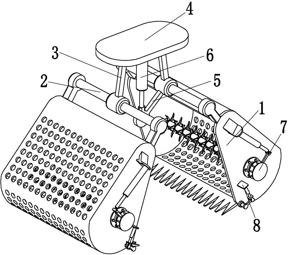
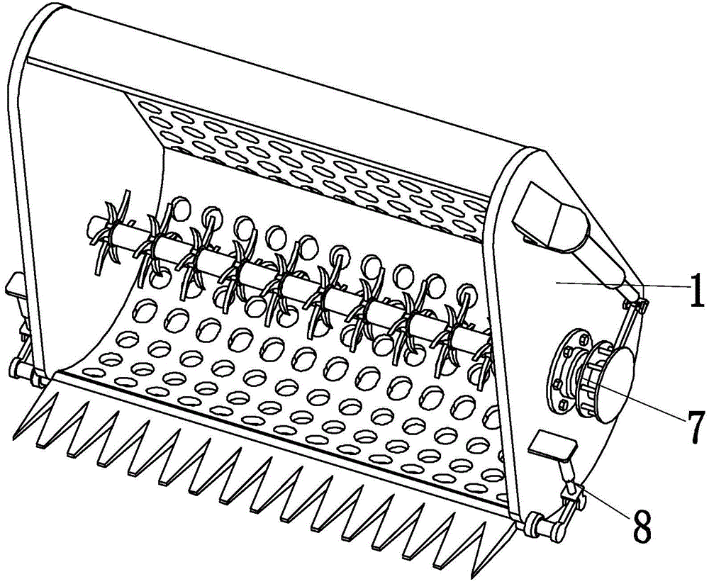
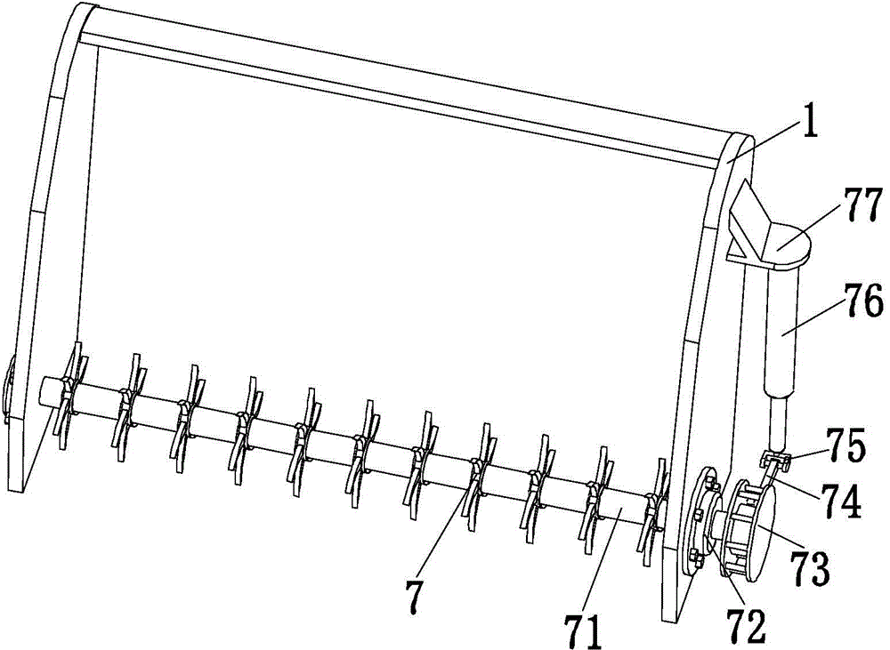
[0022] Such as Figure 1 to Figure 6 As shown, a sieveable gravel grab includes two grab buckets 1, two lower bearing beams 2, two upper supporting rods 3, upper bearing beams 4, two lower supporting rods 5, and a hydraulic cylinder 6 , two stirring and screening devices 7 and two claw head adjusting devices 8, the grab bucket 1 is composed of a left side plate, a right side plate and a main bucket, the left side plate and the right side plate are both shell-shaped structures, the main The bucket has an arc-shaped structure, the left side plate and the right side plate are respectiv...


PUM


Abstract

The invention relates to a screening gravel grab bucket. The screening gravel grab bucket comprises a grab bucket, a lower bearing beam, an upper supporting rod, an upper bearing beam, lower supporting rods, a hydraulic cylinder, stirring screening devices and gripper regulating devices; the lower bearing beam is of an inverted U-shaped structure; the lower bearing beam is fixedly connected with the main bucket of the grab bucket; one end of the upper supporting rod is connected with the lower bearing beam by use of a hinge, while the other end of the upper supporting rod is also connected with the upper bearing beam by use of a hinge; the other ends of two lower supporting rods are connected by use of a movable ear seat; one end of the hydraulic cylinder is connected with the movable ear seat, while the other end of the hydraulic cylinder is connected with the upper bearing beam; two stirring screening devices are mounted inside the main bucket of the grab bucket, respectively; two gripper regulating devices are mounted on the front ends of the main buckets of the grab buckets, respectively. The screening gravel grab bucket is capable of removing sediment mixed with gravel by virtue of stirring and screening in the grabbing process, and therefore, the strength of the constructed building can be improved; the gradient of the gripper of the grab bucket is adjustable so that the volume of the gravel grabbed at a time can be increased and the grabbing efficiency can be improved.

Description

technical field [0001] The invention relates to the field of gravel handling machinery, in particular to a sieveable gravel grab. Background technique [0002] The grab bucket is a bucket that can be opened and closed by grabbing sand, gravel and various bulk goods. It is a spreader that mainly relies on the opening and closing of two combined buckets on the left and right or multiple jaw plates to grab and discharge bulk materials. According to the classification of the shape, the grab can be divided into a shell-shaped grab and a orange-shaped grab. The former is composed of two complete buckets, and the latter is composed of three or more jaw plates; according to the driving method, it can be divided into hydraulic There are two types of grabs and mechanical grabs. [0003] With the rise of the real estate industry in recent years, there are more and more high-rise building construction projects. Stones, an indispensable raw material, are used in house construction. Mixi...

Claims


Application Information

Patent Timeline
Patent Type & Authority Applications(China)
IPC IPC(8): E02F9/00E02F5/30
Inventor 李鹏飞李若愚闫胜昝
Owner 浙江雅迅眼镜科技有限公司
Why Eureka
Try Eureka