
Swirling sand removing device and method

A technology of sand cleaning and axial position, which is used in earth-moving drilling, wellbore/well components, flushing wellbore, etc. Small turbulence and improved sand cleaning effect

Inactive Publication Date: 2015-08-26
YANGTZE UNIVERSITY
View PDF9 Cites 4 Cited by
  • Summary
  • Abstract
  • Description
  • Claims
  • Application Information

AI Technical Summary

Problems solved by technology

Using suction and sand discharge similar to the one-way valve, the existing problems are that the cleaning effect is not ideal, the operation intensity is high, and the sand cleaning process is complicated.
However, the sand cleaning effect of this structure is still not ideal

Method used


Image

  • Swirling sand removing device and method
  • Swirling sand removing device and method
  • Swirling sand removing device and method

Examples


Embodiment 1

[0027] Such as figure 1 Among them, a swirling flow sand cleaning device, the central pipe 2 of the connecting pipe slides and is provided with the central pipe 2, and the tail end of the connecting pipe is connected with the tail joint 1, and the inner diameter of the tail joint 1 is larger than the inner diameter of the connecting pipe. The front end in this case is the figure 1 The right end of the , while the tail refers to the figure 1 in the left end.

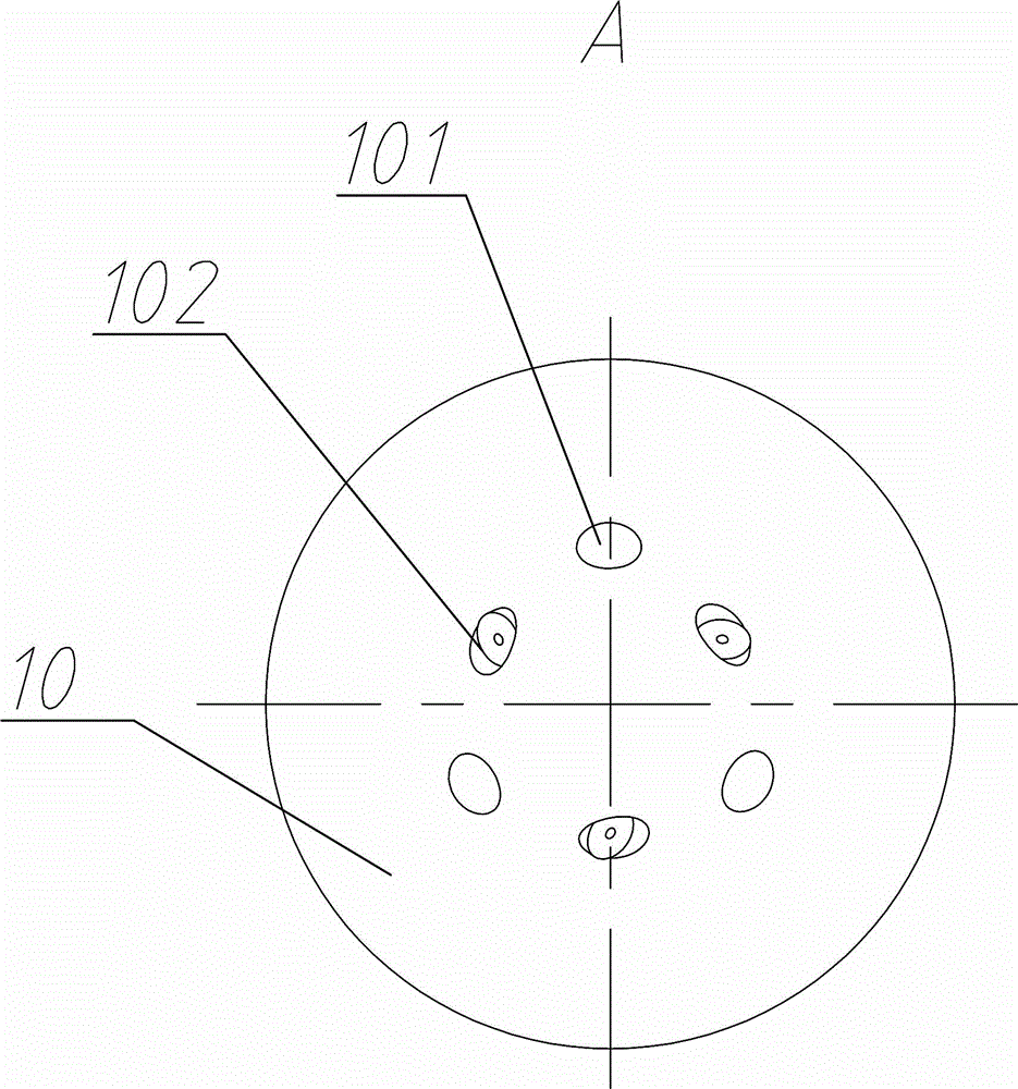
[0028] The front end of the connecting pipe is connected to the rotatable front nozzle assembly 10, and the rear nozzle assembly 5 is arranged on the side wall of the connecting pipe;

[0029] The side wall of the central tube 2 is provided with a side through hole 203. When the central tube 2 is located in an axial position, the side through hole 203 communicates with the rear nozzle hole 51 of the rear nozzle assembly 5; the rear nozzle hole 51 in this example is connected to the connecting pipe Tail sloping.

[003...

Embodiment 2

[0039] A method for performing sand cleaning operations using the above-mentioned swirl sand cleaning device, comprising the following steps: controlling the axial movement of the central pipe 2 with the pressure of the liquid supplied into the connecting pipe, so as to realize the forward rotation of the front spray head assembly 10 to spray liquid and The rear spray head assembly 5 sprays liquid backwards alternately.

[0040] Specifically: when a liquid with a lower pressure is introduced from the tail joint 1, the axial force generated on the center pipe 2 is not enough to make the center pipe 2 overcome the elastic direction of the spring. figure 1 At this time, there is a seal between the side through hole 203 and the rear spray head assembly 5, the liquid pushes away the piston assembly 7, enters the front spray head assembly 10 from the piston through hole 703, and flows from the front spray hole 101 and the rotating When the nozzle 102 is sprayed out, the liquid also ...


PUM


Abstract

The invention provides a swirling sand removing device and a swirling sand removing method. A hollow center pipe is arranged in a connecting pipe in a sliding manner, the front end of the connecting pipe is connected with a rotary front nozzle component, and a rear nozzle component is arranged at the side wall of the connecting pipe; a side through hole is formed in the side wall of the center pipe, and the side through hole is communicated with a rear nozzle of the rear nozzle component when the center pipe is located at an axial position; a piston component is arranged in the connecting pipe, a piston through hole is formed in the piston component, and the piston through hole is communicated with a front nozzle of the front nozzle component; when the central pipe moves axially, the piston is closed or started by the central pipe; a spring which enables the center pipe to be far away from the front nozzle component is further arranged between the central pipe and the connecting pipe. By adopting the structure and the method provided by the invention, the axial movement of the central pipe can be controlled by feeding fluid supply pressure of the connecting pipe, and the forwards rotary liquid injection of the front nozzle component and the backwards liquid injection of the rear nozzle component can be realized, therefore the sand can flow orderly in a shaft bottom, the turbulence is low in the sand removing process, and the sand cleaning effect of the shaft bottom can be improved.

Description

technical field [0001] The invention relates to the field of deep well construction operations, in particular to a cyclone sand cleaning device and method. Background technique [0002] During the development of sandstone oilfields and heavy oil reservoirs, sand production is often encountered in formations. At the same time, during the completion of wells with gravel packing or fracturing, the problem of sand deposits at the bottom of wells often occurs. Formation sand or sand filling will settle and stay in the wellbore to form sand columns and sand beds, which will block the perforation holes and formation channels near the wellbore wall, increase the fluid flow resistance at the bottom of the well, and reduce production. In severe cases, it will affect the normal production of oil wells ; In addition, some workover and stimulation operations require well washing before construction. Therefore, oil and gas wells must use hydraulic sand flushing to remove sand debris depo...

Claims


Application Information

Patent Timeline
Patent Type & Authority Applications(China)
IPC IPC(8): E21B21/00
CPCE21B21/00
Inventor 邓福成谷顺涛
Owner YANGTZE UNIVERSITY
Learn More