
Sand flushing and blockage removal tubular column

A technology for removing plugging and flushing sand, applied in drilling pipes, casings, drilling equipment, etc., can solve problems such as reducing pump efficiency, wearing oil production pumps and pipelines, and stopping production, and achieves the effect of improving connection reliability and reducing installation difficulty.

Active Publication Date: 2019-12-17
CHINA PETROLEUM & CHEM CORP +1
View PDF7 Cites 0 Cited by
  • Summary
  • Abstract
  • Description
  • Claims
  • Application Information

AI Technical Summary

Problems solved by technology

[0003] The sand in the oil well will continue to deposit at the bottom of the well, forming a sand column. When the sand column is too high, it will block the oil outlet channel; and the sand will also wear out various oil production pumps and pipelines, reduce pump efficiency, and reduce production or even stop production of the oil well.

Method used


Image

  • Sand flushing and blockage removal tubular column
  • Sand flushing and blockage removal tubular column
  • Sand flushing and blockage removal tubular column

Examples


Embodiment Construction

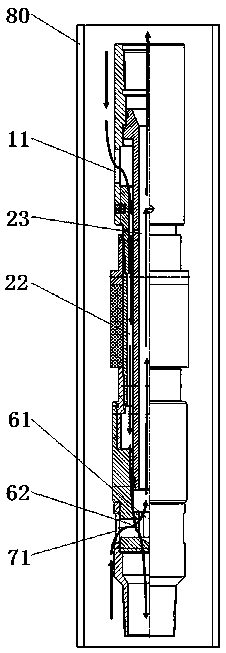
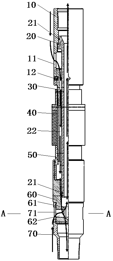
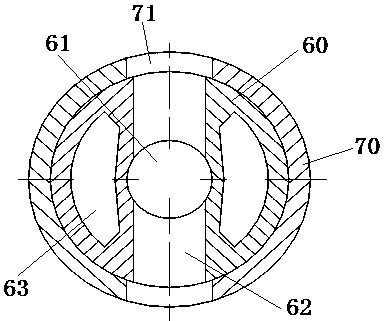
[0031] The specific implementation of the sand flushing and plugging removal pipe string in the present invention will now be described in conjunction with the accompanying drawings.

[0032] As shown in Figure 1, it is an embodiment of the present invention: the relative positional relationship of each structure is represented by the up, down, left, and right directions in the figure. It includes an upper joint 10 , a packer 40 , a bridge joint 60 and a lower joint 70 connected in sequence to cooperate with the base pipe 20 . The upper joint 10 is a sleeve structure with an inner cavity, and the upper joint 10 and the packer 40 are connected through a first variable joint 30. The outer peripheral surface of the first variable joint 30 is provided with external threads, and the packer 40 The ends of the upper joint 10 and the first variable joint 30 are respectively provided with internal threads, and the ends of the upper joint 10 and the packer 40 are all arranged on the fir...


PUM


Abstract

The invention provides a sand flushing and blockage removal tubular column, and the sand flushing and blockage removal tubular column is capable of clearing sand produced in a well to ensure the oil well yield. The sand flushing and blockage removal tubular column comprises a central tube, an upper joint, a packer, a bridge joint and a lower joint; the upper joint is connected with the upper end of the central tube to form an annulus between the upper joint and the central tube; a liquid inlet making the annulus communicate with the space of the upper side of the upper joint is formed in the upper joint; the packer and the upper joint are connected together so as to form an annulus between the packer and the central tube; the bridge joint is connected with the other end of the packer; an annulus is formed between the inner wall of the upper end of the bridge joint and the central tube; a central hole and eccentric holes are formed in the bridge joint; the upper end of the central holecommunicates with an inner cavity of the central tube, and the lower end of the central hole is sealed; lateral holes making the central hole communicate with the space of the outer side of the bridgejoint are further formed in the bridge joint; the upper end of each eccentric hole communicates with annuluses defined by the central tube and the upper joint, the packer and the bridge joint; the lower ends of the eccentric holes communicate with the lower joint; and the central holes and the eccentric holes are isolated by the central tube, and do not communicate with each other.

Description

technical field [0001] The invention relates to the technical field of sand washing tools for oil wells, in particular to a pipe string for sand washing and plugging removal. Background technique [0002] The oil well in the prior art pumps the crude oil in the oil layer into the oil well when it is working. With the increase of the pressure difference inside and outside the oil well, the flow velocity of the crude oil flowing into the well will also increase, and the drag force on the rock becomes larger. When dragging When the force is greater than the tensile strength of the rock, the rock will be damaged by stretching and become sand grains, which will flow into the oil well with the crude oil; When the pressure exceeds the shear stress of the rock, the rock will be sheared and broken into sand grains. As the crude oil flows into the oil well, these sand grains will produce sand in the well after entering the oil well. [0003] The sand particles in the oil well will co...

Claims


Application Information

Patent Timeline
Patent Type & Authority Applications(China)
IPC IPC(8): E21B31/03E21B17/00
CPCE21B17/00E21B31/03
Inventor 乔荣娜刘科伟陈旭波汤程辉王若浩王钊邱勇余铁静
Owner CHINA PETROLEUM & CHEM CORP
Learn More