Cyclone sand cleaning device and method
A technology of sand cleaning and axial position, which is applied in the direction of earthwork drilling, wellbore/well components, and flushing of wellbore, etc. Sand effect, effect with little turbulence
- Summary
- Abstract
- Description
- Claims
- Application Information
AI Technical Summary
Problems solved by technology
Method used
Image
Examples
Embodiment 1
[0026] Such as figure 1 Among them, a swirling flow sand cleaning device, the central pipe 2 of the connecting pipe slides and is provided with the central pipe 2, and the tail end of the connecting pipe is connected with the tail joint 1, and the inner diameter of the tail joint 1 is larger than the inner diameter of the connecting pipe. The front end in this case is the figure 1 The right end of the , while the tail refers to the figure 1 in the left end.
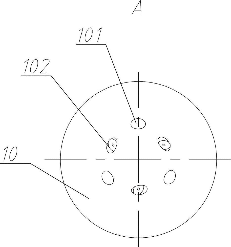
[0027] The front end of the connecting pipe is connected to the rotatable front nozzle assembly 10, and the rear nozzle assembly 5 is arranged on the side wall of the connecting pipe;
[0028] The side wall of the central tube 2 is provided with a side through hole 203. When the central tube 2 is located in an axial position, the side through hole 203 communicates with the rear nozzle hole 51 of the rear nozzle assembly 5; the rear nozzle hole 51 in this example is connected to the connecting pipe Tail sloping.
[002...
Embodiment 2
[0038] A method for performing sand cleaning operations using the above-mentioned swirl sand cleaning device, comprising the following steps: controlling the axial movement of the central pipe 2 with the pressure of the liquid supplied into the connecting pipe, so as to realize the forward rotation of the front spray head assembly 10 to spray liquid and The rear spray head assembly 5 sprays liquid backwards alternately.
[0039] Specifically: when a liquid with a lower pressure is introduced from the tail joint 1, the axial force generated on the center pipe 2 is not enough to make the center pipe 2 overcome the elastic direction of the spring. figure 1 At this time, there is a seal between the side through hole 203 and the rear spray head assembly 5, the liquid pushes away the piston assembly 7, enters the front spray head assembly 10 from the piston through hole 703, and flows from the front spray hole 101 and the rotating When the nozzle 102 is sprayed out, the liquid also ...
PUM
 Abstract
Description
Claims
Application Information
 - R&D
- Intellectual Property
- Life Sciences
- Materials
- Tech Scout
- Unparalleled Data Quality
- Higher Quality Content
- 60% Fewer Hallucinations
Browse by: Latest US Patents, China's latest patents, Technical Efficacy Thesaurus, Application Domain, Technology Topic, Popular Technical Reports.
© 2025 PatSnap. All rights reserved.Legal|Privacy policy|Modern Slavery Act Transparency Statement|Sitemap|About US| Contact US: help@patsnap.com


