Backplane components and backlight modules

A backplane assembly and backlight module technology, applied in optics, light guides, light sources, etc., can solve the problems of optical uniformity and brightness drop, extruded backplane, easy expansion of the light guide plate, etc., and achieve the effect of good light output efficiency.

Inactive Publication Date: 2018-04-10
CORETRONIC (SUZHOU) CO LTD
View PDF9 Cites 0 Cited by
  • Summary
  • Abstract
  • Description
  • Claims
  • Application Information

AI Technical Summary

Problems solved by technology

However, if the gap between the light guide plate and the backplane is too large, the optical uniformity and luminance will be reduced, and the phenomenon of bright bands will easily occur.
Conversely, if the gap between the light guide plate and the backplane is insufficient, the light guide plate will easily expand when heated and squeeze the backplane, causing warping and deformation

Method used


Image

  • Backplane components and backlight modules
  • Backplane components and backlight modules
  • Backplane components and backlight modules

Examples


Embodiment Construction

[0020] The aforementioned and other technical contents, features and effects of the present invention will be clearly presented in the following detailed description of the embodiments with reference to the accompanying drawings. The directional terms mentioned in the following embodiments, such as: up, down, left, right, front or back, etc., are only referring to the directions of the drawings. Accordingly, the directional terms are used to illustrate and not to limit the invention.

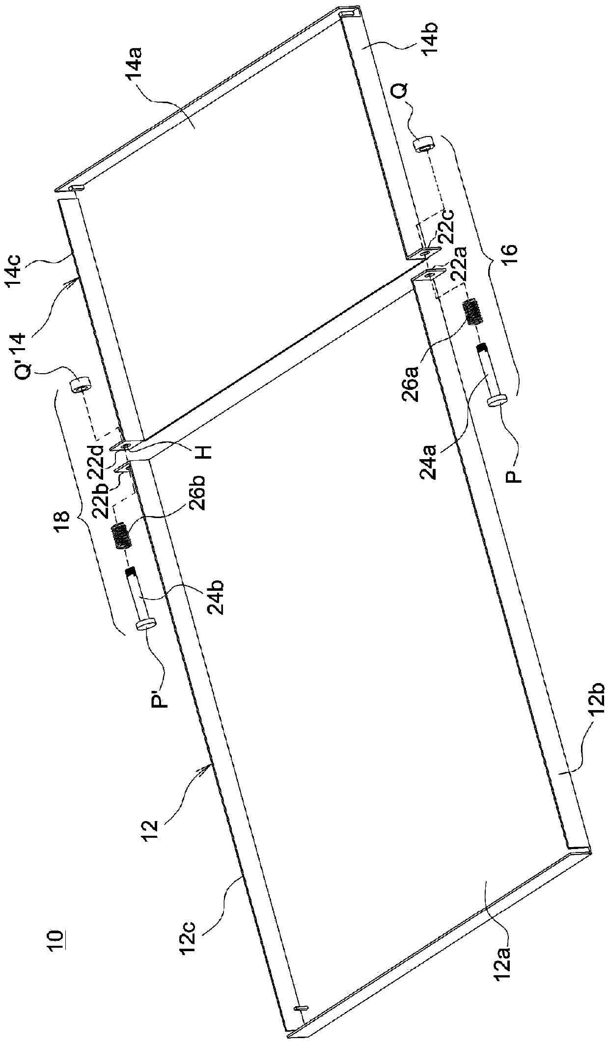
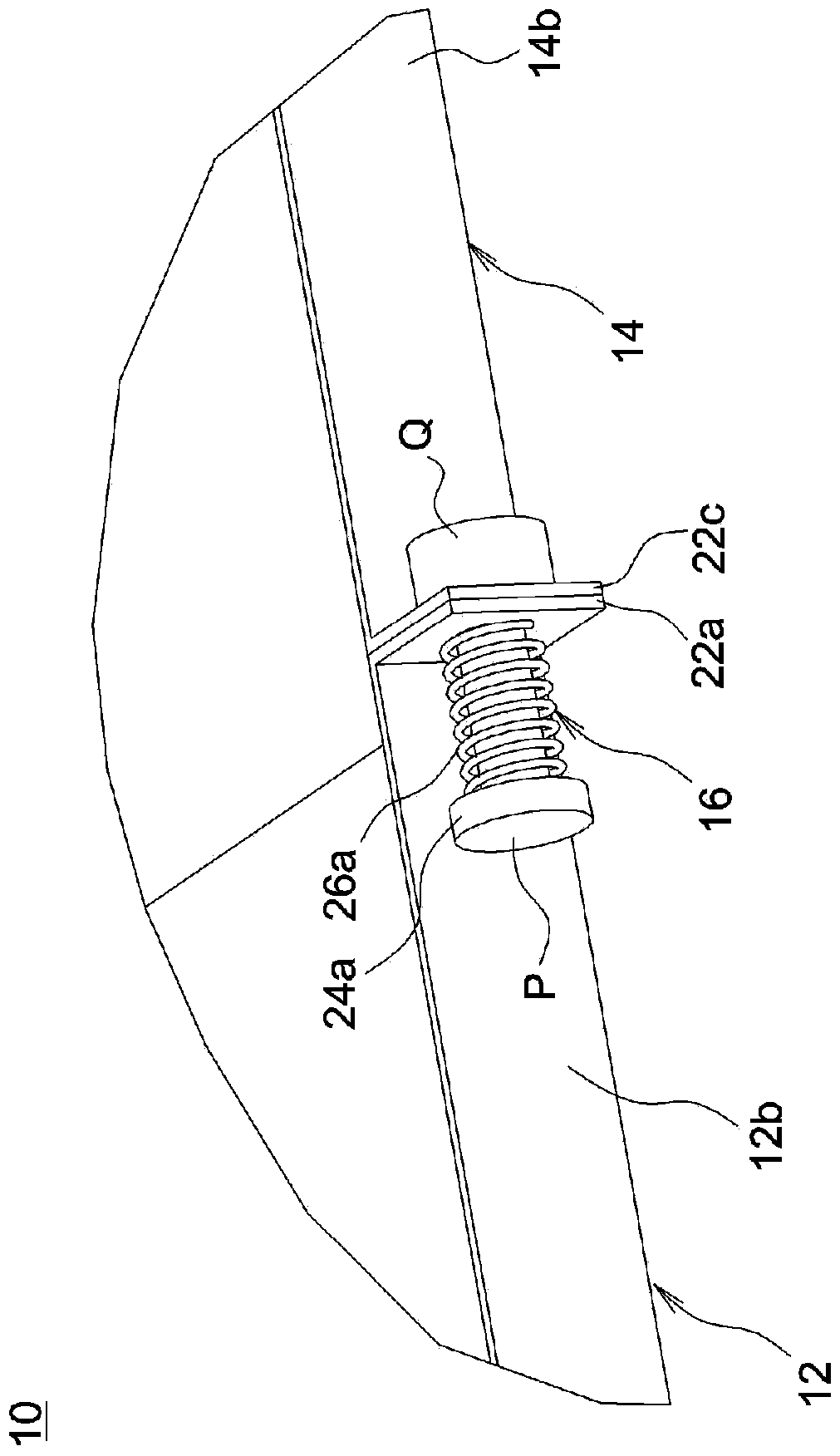
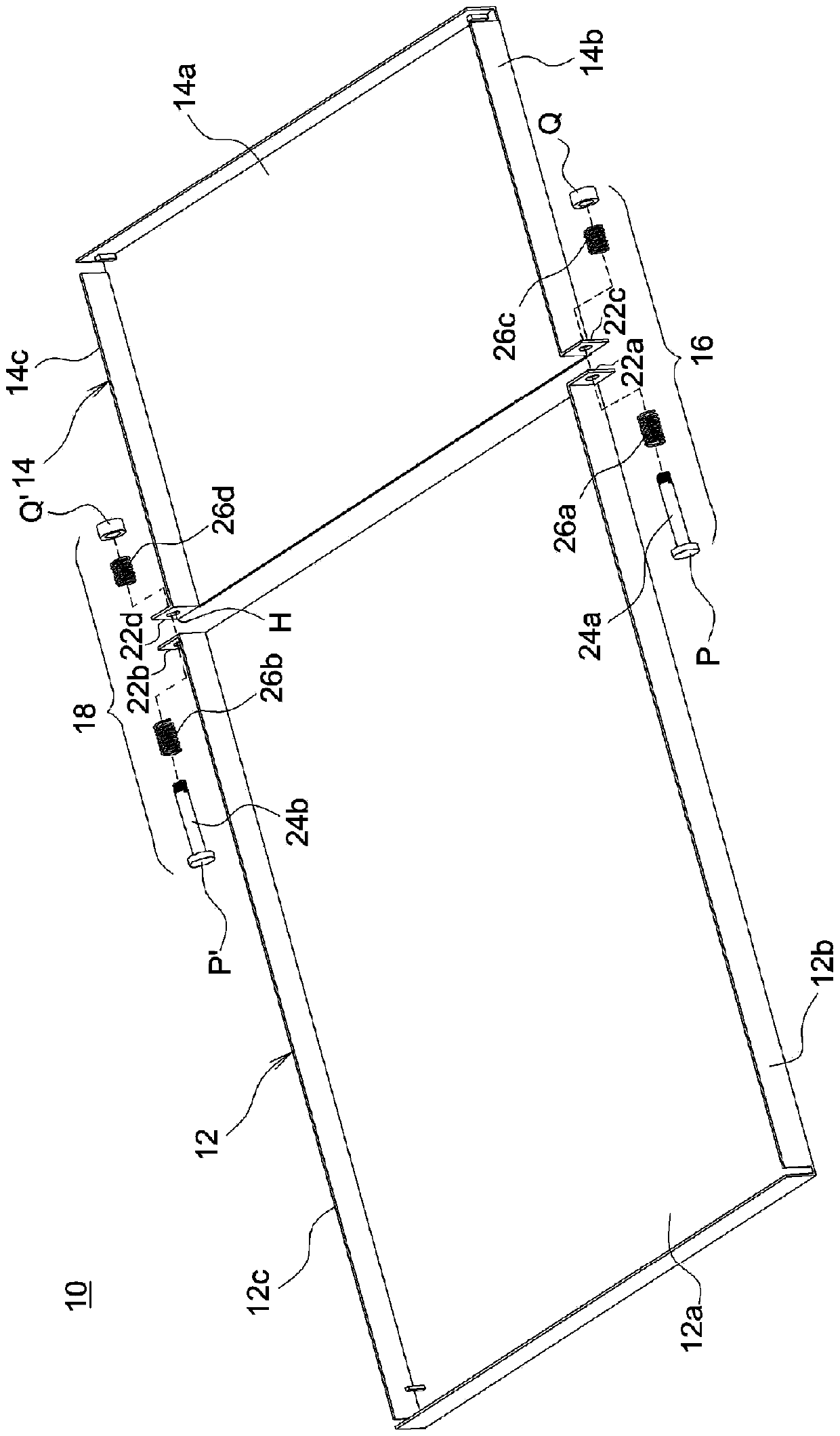
[0021] figure 1 is an exploded view of the components of the backplane assembly according to an embodiment of the present invention, figure 2 for figure 1 The partially enlarged schematic diagram of the backplane assembly after assembly. Please also refer to figure 1 and figure 2 The backplane assembly 10 includes at least a first backplane block 12 and a second backplane block 14 , a first fixing structure 16 , and a second fixing structure 18 . In this embodiment, the first back panel ...


PUM


Abstract

A backplane assembly includes at least two backplane blocks and at least two fixing structures. A bending portion is formed on different sides of each back plate block, and each fixing structure includes a connecting piece and at least one elastic piece. The connecting piece is passed through two adjacent bending parts to connect the first backplane block and the second backplane block, and each elastic piece is sleeved on a connecting piece and limited between one end of the connecting piece and a bending part between.

Description

technical field [0001] The invention relates to a backboard component and a backlight module. Background technique [0002] At present, the backplane used for the backlight module is usually a one-piece structure. Therefore, considering the thermal expansion and contraction, the light guide plate will reserve a movable gap in the backplane to avoid extrusion deformation of the light guide plate due to thermal expansion. However, if the gap between the light guide plate and the backplane is too large, the optical uniformity and luminance will be reduced, and the bright band phenomenon will easily occur. On the contrary, if the gap reserved between the light guide plate and the back plate is insufficient, the light guide plate is easy to expand when heated and press the back plate to cause warping and deformation. [0003] Chinese Patent Publication No. CN102287627A discloses a surface light source device, which includes a light guide plate, two positioning groups, a light so...

Claims


Application Information

Patent Timeline
Patent Type & Authority Patents(China)
IPC IPC(8): F21V21/00F21S8/00F21V19/00F21V8/00G02F1/13357F21Y115/10
CPCF21S8/00F21V17/164F21V21/00
Inventor 王国士
Owner CORETRONIC (SUZHOU) CO LTD
Why Eureka
Try Eureka