Photoelectric sensor

A photoelectric sensor and a technology for detecting light, applied in the field of photoelectric sensors, can solve the problems of photoelectric sensor light-emitting elements, light-receiving elements, resistance differences, etc.

Inactive Publication Date: 2015-08-26
ORMON CORP
View PDF8 Cites 4 Cited by
  • Summary
  • Abstract
  • Description
  • Claims
  • Application Information

AI Technical Summary

Problems solved by technology

In the conventional photoelectric sensor, there is a technique of changing either the gain or the threshold value by using the sensitivity knob, as in the invention of Patent Document 1, but there are individual differences in the light emitting element, light receiving element, resistance, etc. of each photoelectric sensor

Method used


Image

  • Photoelectric sensor
  • Photoelectric sensor
  • Photoelectric sensor

Examples


Embodiment Construction

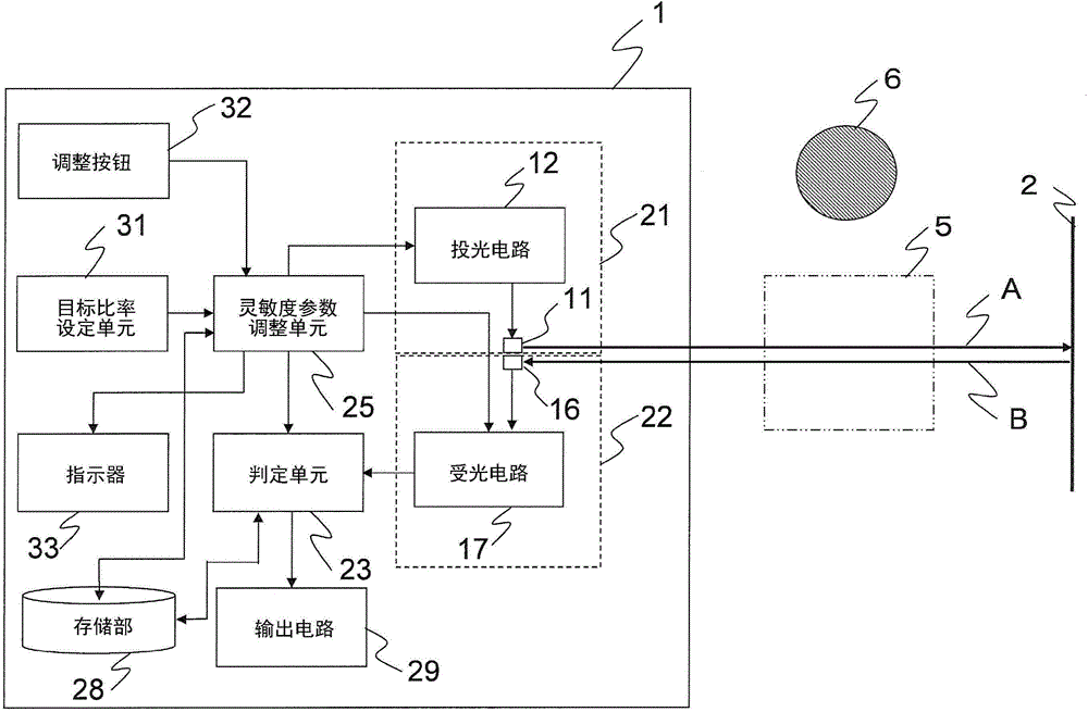
[0021] Next, a photoelectric sensor 1 according to an embodiment of the present invention will be described with reference to the drawings. The photoelectric sensor 1 is a retroreflective photoelectric sensor used in combination with a retroreflective member 2 . figure 1 It is an overall structural diagram of the photoelectric sensor 1.

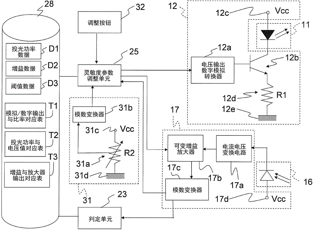
[0022] Such as figure 1 As shown, the photoelectric sensor 1 has a light projecting unit 21 , a light receiving unit 22 , a determination unit 23 , a sensitivity parameter adjustment unit 25 , a storage unit 28 , an output circuit 29 , a target ratio setting unit 31 , an adjustment button 32 and an indicator 33 . figure 2 It is a detailed configuration diagram of the light projecting unit 21 , the light receiving unit 22 , the first adjustment unit 41 , the second adjustment unit 42 , the determination unit 23 and the storage unit 28 .

[0023] The light projecting unit 1 emits detection light A for detecting a detection target object 6 pr...


PUM


Abstract

Provided is a photoelectric sensor capable of easy adjustment for detecting the same detection object. A transmissive photoelectric sensor or a retro-reflective photoelectric sensor includes a light projecting unit, a light receiving unit, a determination unit, a target ratio setting unit, and a sensitivity parameter adjusting unit. The light projecting unit emits detection light for detecting a detection object that is present in a detection region is detected. The light receiving unit receives at least a portion of the detection light emitted by the light projecting means . The determination unit determines whether or not the detection object is present by comparing a received light signal value, which is a signal value of an output of the light receiving unit, with a threshold. The target ratio setting unit sets a target ratio. The sensitivity parameter adjusting unit adjusts a sensitivity parameter so that a ratio of the threshold to the received light signal value is the target ratio, when the detection object is not present in the detection region.

Description

technical field [0001] The present invention relates to photoelectric sensors. Background technique [0002] As one of conventional photoelectric sensors, there is a photoelectric sensor described in Patent Document 1. In this photoelectric sensor, a variable resistor for adjusting the gain of a light-receiving signal is adjusted by a sensitivity knob (a rotatable knob). [0003] prior art literature [0004] patent documents [0005] Patent Document 1: Japanese Patent Laid-Open No. 2002-171162 [0006] It is common to use a photoelectric sensor on a production line, but a plurality of photoelectric sensors are also arranged when the same object to be detected is detected on a production line. When the object to be detected is a transparent object, there is little difference between the amount of light received when the object to be detected is absent and the amount of light received when the object to be detected is present, but it is necessary to set a threshold betwee...

Claims


Application Information

Patent Timeline
IPC IPC(8): G01S17/00
CPCG01V8/12G01V8/14G01S17/00
Inventor 奥浓基晴今井清司植村公辅
Owner ORMON CORP
Why Eureka
Try Eureka