
Current-limiting circuit

A technology of current limiting circuit and power circuit, which is applied in the direction of adjusting electrical variables, control/regulation systems, instruments, etc., can solve the problems of high production cost, low precision of current limiting value, and many circuit components, so as to improve reliability, limit High accuracy of current value and the effect of saving electric energy

Inactive Publication Date: 2015-08-26
史翠萍
View PDF0 Cites 0 Cited by
  • Summary
  • Abstract
  • Description
  • Claims
  • Application Information

AI Technical Summary

Problems solved by technology

[0004] This application aims at the problems of complex structure, numerous circuit components, high production cost, positive temperature coefficient and low accuracy of current limiting value in the existing current limiting circuit, and designs a current limiting circuit

Method used


Image

  • Current-limiting circuit
  • Current-limiting circuit
  • Current-limiting circuit

Examples


Embodiment Construction

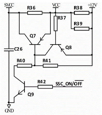
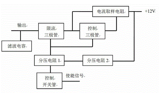
[0013] A current limiting circuit of the present application, such as figure 2 As shown in 3 to 3, it includes two parallel current sampling resistors R38, R39, filter capacitor C26 connected to the output terminal, current limiting transistor Q7, control transistor Q8, control switch transistor Q9, current limiting transistor Q7 and control transistor Q8 are PNP Type transistor, control switch transistor Q9 is NPN type transistor.

[0014] The filter capacitor C26 is grounded; the base of the current-limiting transistor Q7 is connected to the collector of the control transistor Q8; the collector of the current-limiting transistor Q7 is connected to the output terminal; the emitter of the current-limiting transistor Q7 is connected to the output terminal VCC of the power supply circuit; the control transistor The base of Q8 is connected to the output terminal VCC of the power supply circuit, and a voltage dividing resistor R37 is connected in series therebetween; the emitter...


PUM


Abstract

A current-limiting circuit comprises a sampling resistor, a filter capacitor connected with an output terminal, a current-limiting triode, a control triode and a control switch triode, wherein the base electrode of the current-limiting triode is connected with the collecting electrode of the control triode, the emitting electrode of the current-limiting triode is connected with a power supply circuit output terminal, and the collecting electrode of the current-limiting triode is connected with the output terminal; the base electrode of the control triode is connected with the power supply circuit output terminal, and the emitting electrode of the control triode is connected with a +12V power supply; the sampling resistor is connected between the power supply circuit output terminal and the +12V power supply; the emitting electrode of the control switch triode is grounded, the base electrode of the control switch triode is connected with an enable signal end, and a current-limiting resistor is connected in series between the base electrode of the control switch triode and the enable signal end; the collecting electrode of the control switch triode is connected with the base electrode of the current-limiting triode, and a divider resistor is connected in series between the collecting electrode of the control switch triode and the base electrode of the current-limiting triode; the collecting electrode of the control triode is connected with the +12V power supply, and another divider resistor is connected in series between the collecting electrode of the control triode and the +12V power supply. According to the current-limiting circuit, the current-limiting value does not fluctuate along with variation of voltage, is relatively high in precision, has the negative temperature coefficient characteristic, and is reduced along with temperature rise of the circuit, so that the electric energy is saved.

Description

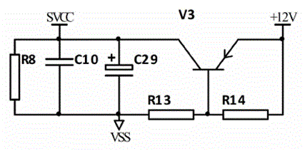
technical field [0001] The present application relates to a current limiting circuit, in particular to a current limiting circuit used in a low-voltage power line carrier communication module. Background technique [0002] The currently known current limiting circuit has complex circuit structure, numerous circuit components, high production cost, positive temperature coefficient, and low accuracy of current limiting value. [0003] Such as figure 1 The current limiting circuit in the carrier module shown in the figure is to limit the maximum current consumption of the carrier module to +12V. If the current amplification factor of the triode HFE=300, the limited output current should not exceed 156mA. When the circuit enters the current limit After mode, the triode V3 will heat up, and the temperature will rise, which will cause the current amplification factor HFE of the triode to increase, so that the output current will increase. The temperature of the triode V3 will co...

Claims


Application Information

Patent Timeline
Patent Type & Authority Applications(China)
IPC IPC(8): G05F1/56
Inventor 史翠萍
Owner 史翠萍
Learn More