USB connector

A technology for connectors and welding strips, applied in the direction of connection, fixed connection, and parts of connection devices, can solve problems such as increased production cost, high product defect rate, adverse effects on transmission performance and mechanical performance, etc., to improve product performance. , the effect of reducing interference

Inactive Publication Date: 2015-08-26
HONG FU JIN PRECISION IND WUHAN CO LTD +1
View PDF0 Cites 1 Cited by
  • Summary
  • Abstract
  • Description
  • Claims
  • Application Information

AI Technical Summary

Problems solved by technology

The structural design of the USB connector makes the processing process complicated, increases the production cost, and the defective rate of the product is high
In addition, the

Method used


Image

  • USB connector
  • USB connector
  • USB connector

Examples


Embodiment Construction

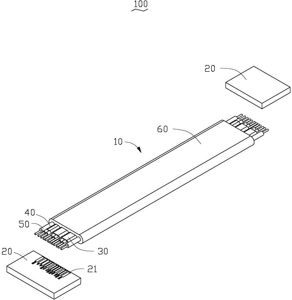
[0020] See figure 1 In a preferred embodiment of the present invention, a USB connector 100 is used for data transmission, and includes two plug connectors (not shown in the figure) and a cable 10.

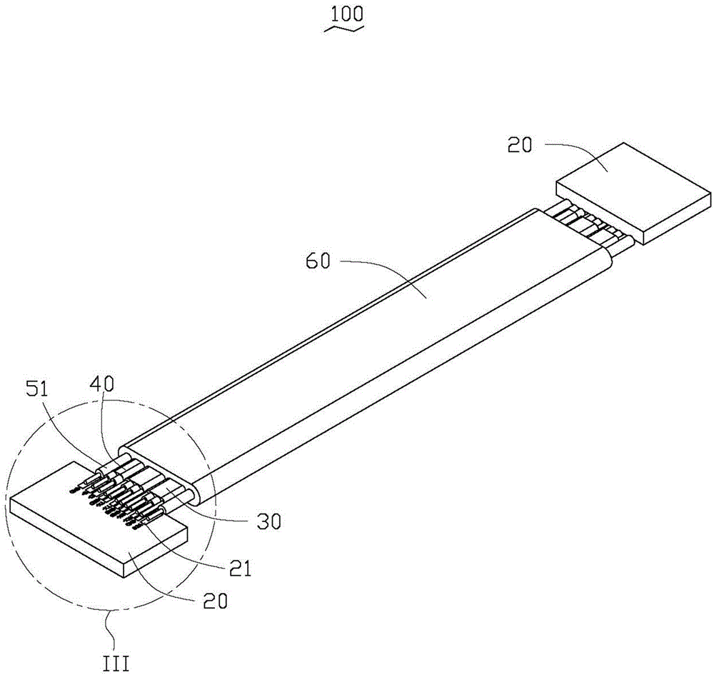
[0021] See figure 2 The plug connector includes an adapter plate 20, and a plurality of welding bars 21 are provided on the adapter plate 20, and the welding bars 21 are used to connect the cable 10 and the adapter plate 20.

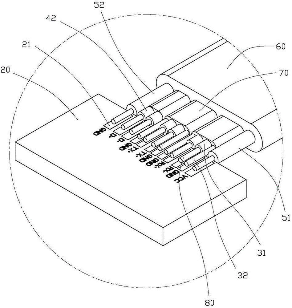
[0022] See figure 2 and image 3 , The cable 10 is flat, the cable 10 includes a plurality of signal line modules and a wire cover 60, the signal line module includes two first signal line modules 30, a second signal line module 40 and a power cord module 50. The first signal line module 30 includes a shielding sleeve 70, two first core wires 31, and two ground wires 32. The two ground wires 32 are located on both sides of the two first core wires 31, respectively. 32 and the two first core wires 31 are arranged in parallel to each other, the two ground wires ...


PUM


Abstract

A USB connector comprises a plug-in joint and a cable. The plug-in joint is provided with a switching board. The switching board is provided with a plurality of welding strips. The cable comprises a plurality of signal line modules. The signal line modules are parallel to each other and approximately arranged in one plane. Each signal line module can be fixed to the welding strip corresponding to the switching board.

Description

Technical field [0001] The invention relates to a connector, in particular to a USB connector. Background technique [0002] USB (Universal Serial Bus, Universal Serial Bus) connectors are widely used in the data transmission and charging fields of electronic products. In order to meet the development requirements of miniaturization and multi-function of electronic products, new types of USB connectors are constantly being developed , Such as the USB3.0 series connector. At present, due to the limitation of the structure of the USB connector, the core wire of the USB connector needs to be covered with a heat-shrinkable tube, and it is also necessary to use a core pliers to remove the insulators at the end of each core wire one by one, and then remove each core Wire and terminal are welded one by one, and then the inner mold is injected to protect the welding part of the connector. The structural design of the USB connector makes its processing technology complex, increases prod...

Claims


Application Information

Patent Timeline
IPC IPC(8): H01R12/59H01R13/6461H01B7/17
CPCH01R12/61H01B7/17H01R13/6461
Inventor 朱志明罗明辉王婷
Owner HONG FU JIN PRECISION IND WUHAN CO LTD
Why Eureka
Try Eureka