Patella prosthesis

A patella prosthesis and patella technology, applied in the field of medical equipment, can solve the problem that the patella prosthesis cannot achieve a buffering effect, and achieve the effects of improving life expectancy, reducing pain and reducing wear and tear.

Active Publication Date: 2015-09-02
BEIJING AKEC MEDICAL
View PDF10 Cites 0 Cited by
  • Summary
  • Abstract
  • Description
  • Claims
  • Application Information

AI Technical Summary

Problems solved by technology

[0004] The main purpose of the present invention is to provide a patella prosthesis to solve

Method used


Image

  • Patella prosthesis
  • Patella prosthesis
  • Patella prosthesis

Examples


Embodiment Construction

[0024] It should be noted that, in the case of no conflict, the embodiments in the present application and the features in the embodiments can be combined with each other. The present invention will be described in detail below with reference to the accompanying drawings and examples.

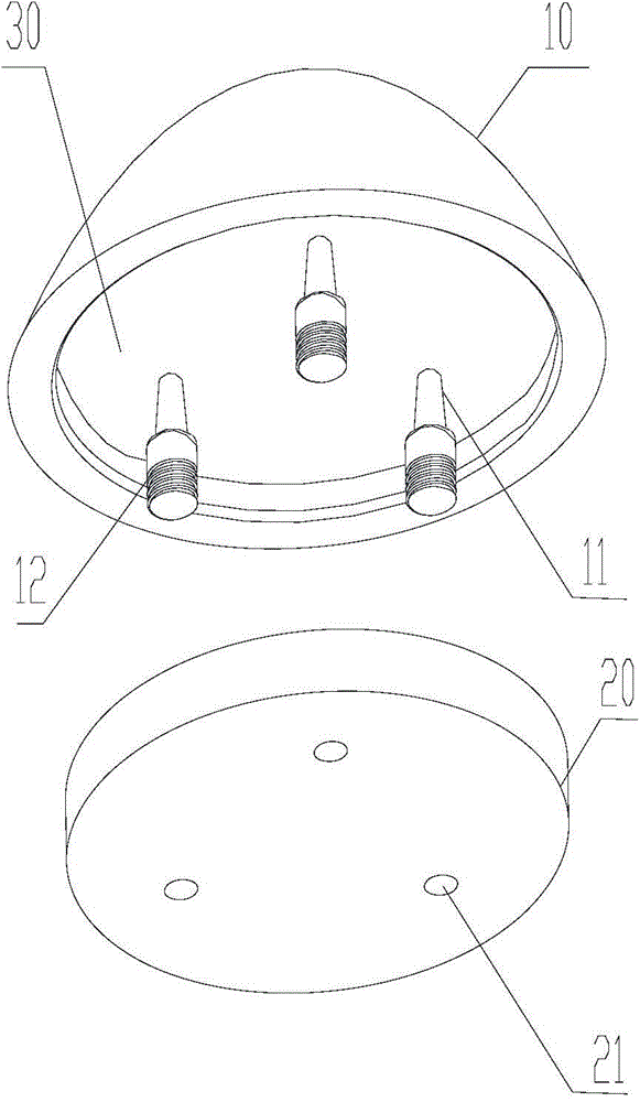
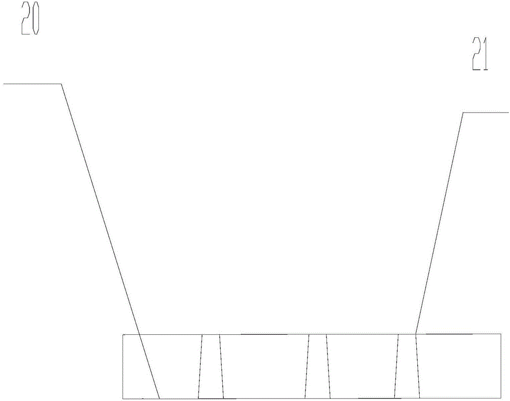
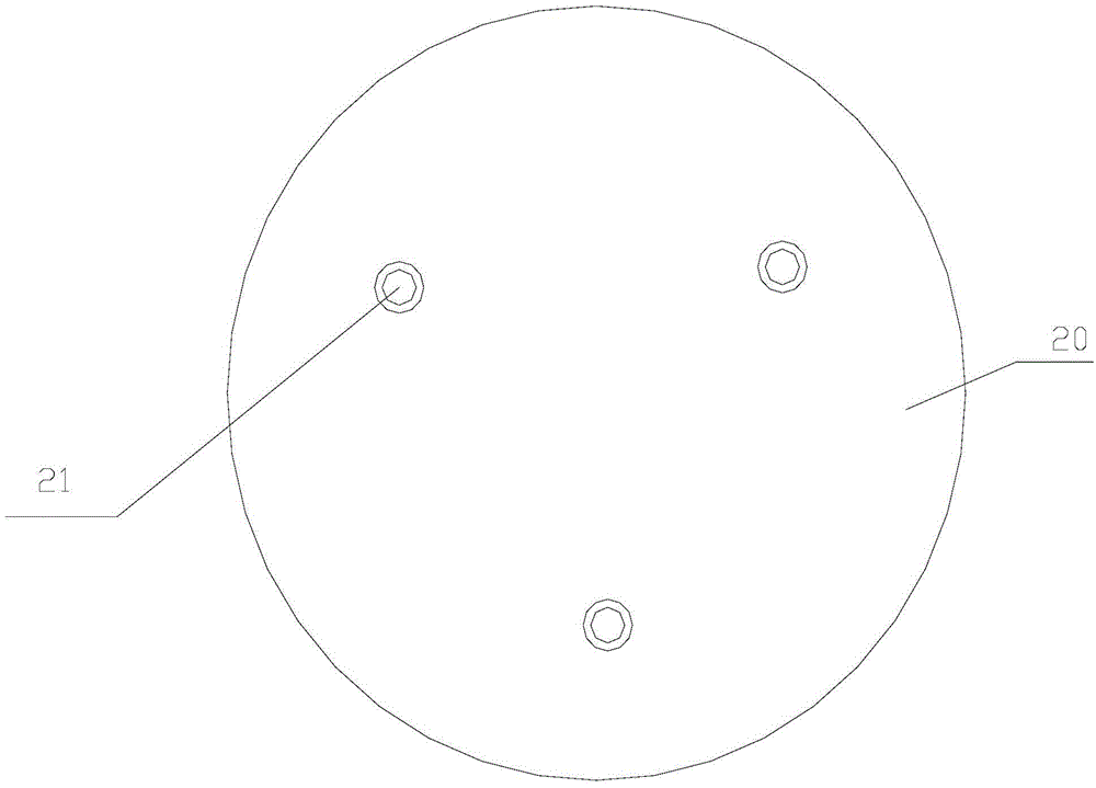
[0025] Such as figure 1 As shown, the present invention provides a patella prosthesis including a patella body 10 and an elastic component 20 . The patella main body 10 has a force-receiving side and a connecting side, and the connecting side of the patella main body 10 is provided with a connecting part. The elastic member 20 is disposed on the connection side of the patella body 10 .

[0026] In this embodiment, the connection part and the elastic component 20 are arranged on the connection side of the patella prosthesis, so that the combined patella prosthesis is more elastic. The provided elastic component 20 can disperse the stress of the femur on the patella, reduce the wear of the pat...


PUM


Abstract

The invention provides a patella prosthesis. A patella main body is provided with a load-bearing side and a connecting side, and the connecting side of the patella main body is provided with a connecting part and an elastic part; by arranging the connecting part and the elastic part on the connecting side of the patella prosthesis, the combined patella prosthesis is more elastic. Stress conducted by a femur on a patella can be dispersed according to the arranged elastic part, the abrasion of the patella prosthesis and a femur prosthesis is reduced, the service life of the patella prosthesis is prolonged, and the pain of a patella ligament of a human body is relieved.

Description

technical field [0001] The invention relates to the technical field of medical equipment, in particular to a patella prosthesis. Background technique [0002] In the normal human knee joint, the upper and lower ends of the patella are attached to the quadriceps femoris and the patellar ligament respectively, which are the key parts of the knee extension mechanism and play the role of a fulcrum in the process of knee extension. The fat pad is located below the patella and behind the patellar ligament. The fat pad has a shock-absorbing effect, can effectively reduce the friction between the patella ligament and the articular surface of the bone, and ensure the normal trajectory of the patella. The contact with the femoral condyle in the prior art is rigid contact, that is, the femoral prosthesis of polyethylene is in rigid contact with the femoral condyle of metal. The polyethylene material of the patella prosthesis plays a weak elastic role and does not achieve the cushionin...

Claims


Application Information

Patent Timeline
IPC IPC(8): A61F2/38
Inventor 刘敏
Owner BEIJING AKEC MEDICAL
Why Eureka
Try Eureka