
Punching and trimming die

A trimming die and blanking technology, which is applied in the field of hot-formed steel plate punching, can solve the problems of large punching force and cannot meet the use of small-tonnage equipment, so as to reduce the punching force of the mold, save the laser cutting process, The effect of reducing equipment energy consumption

Inactive Publication Date: 2015-09-02
上海凌云汽车模具有限公司
View PDF9 Cites 1 Cited by
  • Summary
  • Abstract
  • Description
  • Claims
  • Application Information

AI Technical Summary

Problems solved by technology

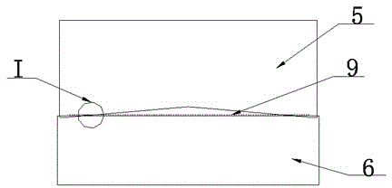
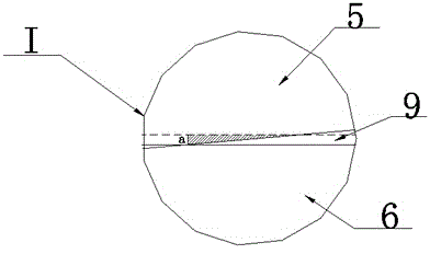
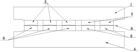
But in the existing punching and trimming die, all trimming upper knife 5 punching work starts simultaneously, finishes simultaneously, as image 3 , if the trimming length is longer and there are more knives 5 on the trimming, the punching force is also very large, which still cannot meet the needs of small-tonnage equipment

Method used


Image

  • Punching and trimming die
  • Punching and trimming die
  • Punching and trimming die

Examples


Embodiment approach 1

[0023] This embodiment provides a punching and trimming die, such as Figure 4 and 5 As shown, the pressing core 2 is installed in cooperation with the upper die base 1, and the nitrogen spring 3 is installed between the upper die base 1 and the pressing core 2 to provide power for the movement of the pressing core 2 in the upper die base 1, and also for When the upper die base 1 is descending, the pressing core 2 presses the workpiece 9 to provide pressure, and the two rows of trimming upper knives 5 are fixed on the bottom of the upper die base 1 in parallel through threaded connections, and there are five in each row. The trimming upper knives 5 (respectively 5-1, 5-2, 5-3, 5-4 and 5-5) distributed symmetrically in a stepped shape on the lower surface, the middle trimming upper knife 5-1 on the lower surface The lowest position, the position of the lower surface of the upper trimming knife on both sides rises in turn (5-2 and 5-3 equal height, 5-4 and 5-5 equal height), co...

Embodiment approach 2

[0027]This embodiment is a further improvement of Embodiment 1. The main improvement is that in this embodiment, an upper knife backing plate 7 is respectively fixed between the upper surface of each trimming upper knife 5 and the upper mold base 1, such as Figure 4 and 5 , by changing the thickness of the upper knife backing plate 7, the punching stroke of each trimming upper knife 5 can be adjusted conveniently. The thickness of the edge trimming upper knife 5 is adjusted, and the introduction of the upper knife backing plate 7 can also play a buffer role to prevent the upper die base 1 from being punched and deformed under large punching force; in addition, the lower edge of each trimming lower knife 6 The lower knife backing plate 8 is also fixed between the surface and the lower die base 4 respectively. The introduction of the lower knife backing plate 8 is mainly to prevent the lower die base 4 from being punched and deformed under the large punching force, and at the s...


PUM


Abstract

The invention relates to the technical field of thermal forming steel plate punching and discloses a punching and trimming die. The punching and trimming die is characterized in that a pressing core (2) and an upper die base (1) are mounted in a matched manner, a nitrogen spring (3) is mounted between the upper die base (1) and the pressing core (2), upper trimming cutters (5) in each row are fixed at the bottom of the upper die base (1) sequentially, the lower surfaces of the upper trimming cutters (5) in each row are in stepped distribution, lower trimming cutters (6) corresponding to the upper trimming cutters (5) are fixed on the upper portion of a lower die base (4) sequentially, and the upper trimming cutters (5) and the lower trimming cutters (6) are in staggered arrangement. The punching and trimming die has the advantages that a part to be punched can be subjected to nibbling, and die punching force is decreased effectively, so that cold punching and trimming of large high-strength thermal-forming parts are simpler and more reliable, cost is low, tonnage of a punching press is decreased greatly, cold punching and trimming of larger thermal-forming parts becomes possible, and equipment energy consumption and production cost are low.

Description

Technical field [0001] The invention involves the field of hot -forming steel plate breeding technology, and specially involves a type of tailoring mold. Background technique [0002] The thermal stamping molding is to heat the boron steel plate (the initial strength is 500 ~ 600MPa) to 900 ° C, so that it reaches the status of the Austrian body, and then quickly transfer to the high -speed stamping molding in the mold.The cooling speed of / s has a period of time to obtain the molding technology of ultra -high -strong steel plate parts with uniform horse austed tissue and strength of 1400 ~ 1600MPa.In the high temperature state, the production environment has a greater impact on its sideline size, and most thermal molding components have strict requirements on the size of the sideline. For exampleThe edge is required to cut the edge tolerance ± 0.5mm. Thermal formation of thermal formation cannot meet such a tolerance requirement, and the cut -edge process needs to be added. [0...

Claims


Application Information

Patent Timeline
Patent Type & Authority Applications(China)
IPC IPC(8): B21D28/14
CPCB21D28/14
Inventor 李立臣刘焱森辛宪秀张伟良申鹏
Owner 上海凌云汽车模具有限公司
Learn More