Flat sanding method, arc sanding machine and flat sanding line

A curved plate and assembly line technology, which is applied in the direction of abrasive jetting machine tools, used abrasive processing devices, abrasives, etc., to achieve the effect of ensuring the sanding effect

Active Publication Date: 2017-11-21
GUANGDONG XINHUI CIMC SPECIAL TRANSPORT EQUIPS
View PDF1 Cites 0 Cited by
  • Summary
  • Abstract
  • Description
  • Claims
  • Application Information

AI Technical Summary

Problems solved by technology

[0005] The invention provides a flat sanding method, an arc-shaped sanding machine and a flat sanding assembly line, so that the sanding machine can solve the sanding problem of wider plates on the basis of the existing width unchanged, and after sanding The sand accumulated on the plate can slide freely to ensure the sanding effect

Method used


Image

  • Flat sanding method, arc sanding machine and flat sanding line
  • Flat sanding method, arc sanding machine and flat sanding line
  • Flat sanding method, arc sanding machine and flat sanding line

Examples


Embodiment Construction

[0032] Typical embodiments that embody the features and advantages of the present invention will be described in detail in the following description. It should be understood that the present invention is capable of various changes in different embodiments without departing from the scope of the present invention, and that the description and illustrations therein are illustrative in nature and not limiting. this invention.

[0033] The flat plate sanding method, curved plate sanding machine and flat plate sanding assembly line of the present invention are applicable to steel plates or other similar plates that need to be sanded, and are introduced one by one as follows.

[0034] Embodiment of flat sand blasting method

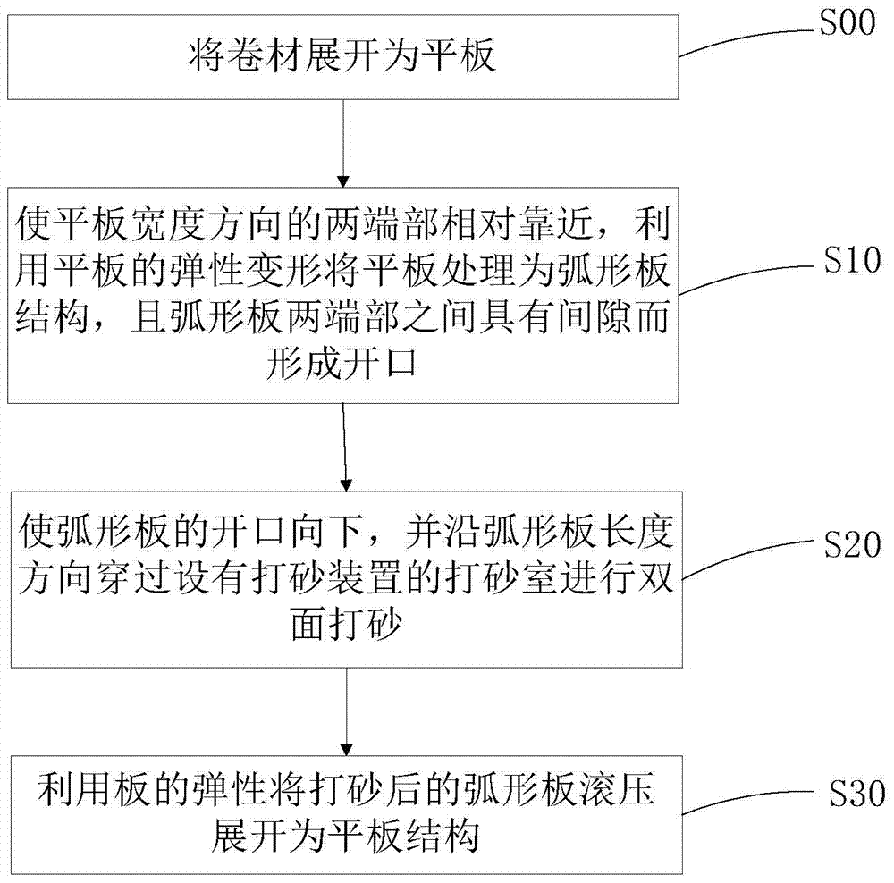
[0035] refer to figure 1 , the present invention at first provides a kind of flat sanding method, comprises steps:

[0036] S00: Unfold the coiled material into a flat plate; this step is applicable to the case where the raw material is a coiled material, an...


PUM

PropertyMeasurementUnit
diameteraaaaaaaaaa

Abstract

The invention provides a flat plate sanding method, an arc plate sanding machine and a flat plate sanding production line. The sanding method includes steps of: S10, enabling two end parts of a flat plate in the width direction to get close to each other, and treating the flat plate into an arc plate structure, and a gap between the two end parts of the arc plate forming an opening; and S20, enabling the opening of the arc plate to face downward, and enabling the arc plate to pass through a sanding chamber provided with a sanding device in the length direction of the arc plate for double-face sanding. The sanding treatment of the flat plate with greater width can be realized in the sanding machine of the invention approximately as wide as a conventional common sanding machine, and after sanding, all the sand on both surfaces of the plate can free slide down, and the sanding effect is ensured.

Description

technical field [0001] The invention relates to the field of plate surface treatment, in particular to a flat plate sanding method, a curved plate sanding machine and a flat plate sanding assembly line. Background technique [0002] The existing steel plate sanding machine is mainly composed of a steel plate conveying structure and a mechanical shot blasting machine. The steel plate passes through several (generally one to six) main bodies of the sanding machine under the drive of the conveying mechanism, and each main body has two shot blasting machines on the upper and lower sides. The device performs mechanical sandblasting on the steel plate to achieve the purpose of surface treatment. The main body of the sand blasting machine is equipped with a dust collector to deal with the dust generated by sand blasting. During the whole operation process, the steel plate on the conveying mechanism is placed horizontally, and the shot blaster blasts sand on the upper and lower sur...

Claims


Application Information

Patent Timeline
Patent Type & Authority Patents(China)
IPC IPC(8): B24C3/18B24C5/00B24C9/00B24C1/00
CPCB24C1/08B24C3/12B24C3/18B24C5/00B24C9/00
Inventor 姚谷赵建刚
Owner GUANGDONG XINHUI CIMC SPECIAL TRANSPORT EQUIPS
Why Eureka
Try Eureka