Clamping device

A clamping device and clamping block technology, applied in workpiece clamping devices, manufacturing tools, etc., can solve the problems of cumbersome operation, slow speed, easy to pinch the surface of parts, etc., achieve reliable clamping method, and increase the scope of application Effect

Inactive Publication Date: 2015-09-02
SHENGRUI TRANSMISSION
View PDF8 Cites 13 Cited by
  • Summary
  • Abstract
  • Description
  • Claims
  • Application Information

AI Technical Summary

Problems solved by technology

[0004] The object of the present invention is to provide a clamping device capable of quickly, easily and reliably clamping cylindrical parts with different diameters, so as to solve the problem that the existing tooling for fixing cylindrical parts requires manual operation, cumbersome operation, slow speed and difficult clamping. The effect is not good and it is easy to pinch the surface of the part during the clamping process

Method used


Image

  • Clamping device
  • Clamping device
  • Clamping device

Examples


Embodiment Construction

[0026] In order to make the object, technical solution and advantages of the present invention clearer, the present invention will be further described in detail below in conjunction with the accompanying drawings and embodiments. It should be understood that the specific embodiments described here are only used to explain the present invention, not to limit the present invention.

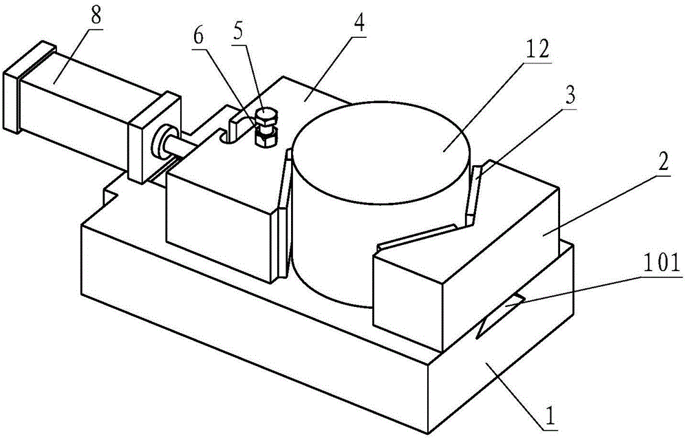
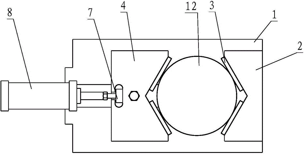
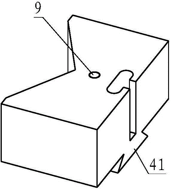
[0027] The first embodiment of the present invention is as figure 1 and figure 2 shown. The clamping device includes a base 1 , a first clamping block 2 and a second clamping block 4 . The base 1 is provided with a dovetail groove 101, and the second clamping block 4 is provided with a dovetail guide rail 41 adapted to the dovetail groove 101 on the base 1, such as image 3 shown. The first clamping block 2 is provided with a V-shaped groove, the opening angle of the V-shaped groove is 120°, and a rubber gasket 3 is fixed on the slope of the V-shaped groove; the second clamping block 4 and the...


PUM


Abstract

The invention belongs to the technical field of tooling for part assembling and discloses a clamping device. The clamping device comprises a base, a first clamping block and a second clamping block, the first clamping block is mounted on the base and provided with a V-shaped groove, rubber gaskets are arranged on inclined faces of the V-shaped groove, and the second clamping block is in sliding connection with the base and connected with a clamping power device. The clamping device is capable of clamping different diameters of cylindrical parts quickly, conveniently, simply and reliably and solving the problems that an existing tooling for fixing cylindrical parts needs manual operation and is complex to operate, low in speed, poor in clamping effect and prone to damaging part surfaces during clamping, and thereby being widely applicable to clamping of cylindrical parts during assembling production.

Description

technical field [0001] The invention relates to the technical field of tooling in parts assembly, in particular to a clamping device. Background technique [0002] In the process of equipment assembly, it is often necessary to clamp cylindrical parts. For example, in the process of assembling the water pump assembly, the pulley needs to be fixed to facilitate the installation of other parts. The conventional operation is to clamp the pulley with a vise. This process Two people are required to operate at the same time, one person moves the piece, and one person operates the bench vise, which is time-consuming, laborious and labor-intensive. And because the jaws of the bench vise are flat, the pulley is cylindrical, and there is a line contact between the pulley and the jaws, there are only two clamping points, which restrict the degree of freedom less, and it is easy to cause poor clamping; and because the workpiece and the vise There is a line contact between the mouths, th...

Claims


Application Information

Patent Timeline
Patent Type & Authority Applications(China)
IPC IPC(8): B25B11/02
CPCB25B11/02
Inventor 张淑燕
Owner SHENGRUI TRANSMISSION
Why Eureka
Try Eureka