A Universal Angle Fixture for Numerical Control Center

A CNC center and universal technology, applied in the direction of clamping, manufacturing tools, metal processing machinery parts, etc., can solve the problems of high cost of tooling and fixture design and manufacturing, low clamping, processing efficiency, and complex parts structure, etc., to reduce duplication The trouble of clamping, high versatility, and the effect of improving firmness

Active Publication Date: 2020-11-27
安庆市基丞精密机械有限公司
View PDF7 Cites 0 Cited by
  • Summary
  • Abstract
  • Description
  • Claims
  • Application Information

AI Technical Summary

Problems solved by technology

[0003] Due to the complex structure and changeable angles of parts, traditional fixtures generally can only meet the processing needs of one angle, which makes the design and manufacturing costs of fixtures higher, and the efficiency of clamping and processing is low, and it is not easy to use.

Method used


Image

  • A Universal Angle Fixture for Numerical Control Center
  • A Universal Angle Fixture for Numerical Control Center
  • A Universal Angle Fixture for Numerical Control Center

Examples


Embodiment Construction

[0026] Through the description of the embodiments below, the specific implementation of the present invention includes the shape, structure, mutual position and connection relationship between the various parts, the function and working principle of each part, the manufacturing process and the operation and use method of the various components involved. etc., to make further detailed descriptions to help those skilled in the art have a more complete, accurate and in-depth understanding of the inventive concepts and technical solutions of the present invention. ", "Bottom", "Front", "Back", "Left", "Right", "Inner", "Outer", "Side", etc., are only for reference to the direction and position of the attached drawing, therefore, the used The terms of direction and position are used to illustrate and understand the present invention, but not to limit the present invention.

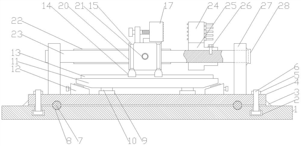
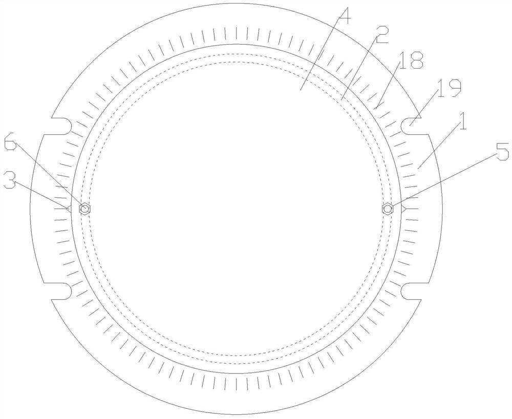
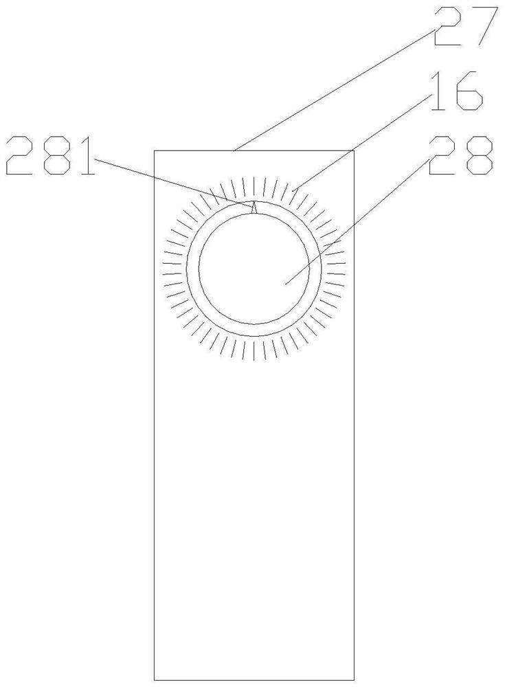
[0027] Figure 1-7 Shown is a kind of universal corner fixture for numerical control center, which includes...


PUM


Abstract

The invention discloses a universal angle clamp for a numerical control center. The universal angle clamp comprises a chassis and a concentric rotary plate; the upper end surface of the chassis and the lower end surface of the rotary plate are provided with annular and concentric semicircular grooves; the semicircular grooves are internally provided with balls; the middle of the rotary plate is provided with a sleeve; a support rod is slidably connected into the sleeve; a support plate is arranged at the upper end of the support rod; lifting devices are arranged on the lower portions of the two sides of the support plate; the support plate is provided with a first sliding rail in the length direction of the support plate; two slidably-connected sliding clamping blocks are arranged on the first sliding rail; the two ends of the rotary plate are provided with rotating bases; a rotating shaft is fixed to the inner rings of the rotating bases; the two ends of the rotating shaft are sleevedwith a sliding sleeve and a fixed sleeve correspondingly; the upper end of the fixed sleeve is provided with a second clamping body; two trapezoidal grooves are formed in the outer wall of the sliding sleeve circumferentially; and a first clamping body is arranged at the upper end of the sliding sleeve. The clamp is applicable to machining of any surface of complicated parts, the adjustment method is simple, the cost for redesigning special clamps for complex parts is reduced, the machining efficiency is improved, and the clamping force on the complex parts is increased.

Description

technical field [0001] The invention belongs to the technical field of fixtures, and in particular relates to a universal corner fixture for a numerical control center. Background technique [0002] In modern metal machining, CNC centers that can automatically change tools are often used, among which three-axis processing is the main one. For complex parts with inclined surfaces and inverted slopes, three-axis CNC centers cannot directly process them, and auxiliary fixtures need to be designed to assist Clamp the workpiece so that the workpiece can be well positioned. [0003] Due to the complex structure and variable angles of parts, traditional fixtures can only meet the processing needs of one angle, which makes the design and manufacturing costs of fixtures higher, and the efficiency of clamping and processing is low, and it is not easy to use. Contents of the invention [0004] According to the deficiencies of the prior art above, the technical problem to be solved b...

Claims


Application Information

Patent Timeline
Patent Type & Authority Patents(China)
IPC IPC(8): B23Q3/06B23Q7/00
CPCB23Q3/06B23Q7/00
Inventor 孙涛赵峰王子彬张玲牛敬仁潘克福
Owner 安庆市基丞精密机械有限公司
Why Eureka
Try Eureka