Limiting device of electric trolley of bridge type crane

A technology of bridge cranes and electric trolleys, which is applied in the direction of traveling mechanism, transportation and packaging, and load hanging components, etc. It can solve the problems of large impact force, inability to make full use of the crane space, and lack of protection, etc., to achieve service life Long, good braking effect, ensure the effect of stability

Active Publication Date: 2015-09-02
HENAN HENGYUAN HENGSHAN IND CO LTD
View PDF6 Cites 10 Cited by
  • Summary
  • Abstract
  • Description
  • Claims
  • Application Information

AI Technical Summary

Problems solved by technology

[0002] The electric trolley in the bridge crane needs limit protection during operation to prevent the electric trolley from running to the limit position and violent collision with the car block, which plays a vital role in the safety protection of the crane. The traditional electric trolley runs The mechanism use

Method used


Image

  • Limiting device of electric trolley of bridge type crane
  • Limiting device of electric trolley of bridge type crane
  • Limiting device of electric trolley of bridge type crane

Examples


Embodiment 1

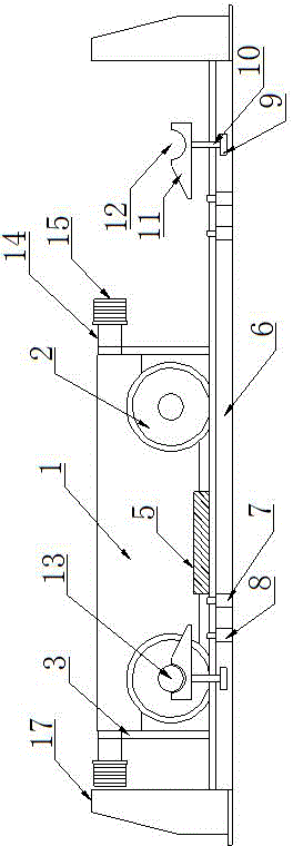
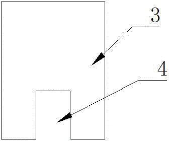
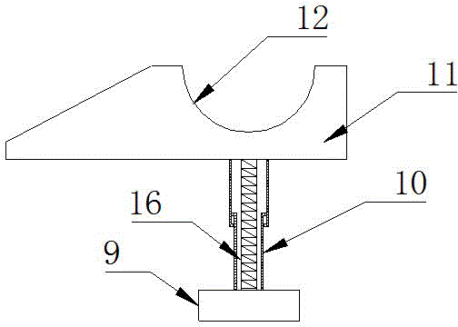
[0020] Such as Figure 1-3 As shown, a limit device for an electric trolley of a bridge crane, which includes a vehicle frame 1 and wheels 2, the left and right ends of the vehicle frame 1 are provided with sweeping rail plates 3, and the lower end of the described rail sweeping plate 3 is provided with Notch 4, a safety ruler 5 is provided at the center of the lower part of the vehicle frame 1, a running track 6 is set under the wheel 2, and a proximity switch group is symmetrically arranged on the left and right ends of the running track 6, and the The proximity switch group includes the proximity switch A7 arranged on the inside and the proximity switch B8 on the outside. The front side of the running track 6 on the outside of the proximity switch B8 is provided with a fixed seat 9, and the upper side of the fixed seat 9 is provided with a The telescopic tube 10, the top of the telescopic tube 10 is provided with a brake block 11, and the brake block 11 is provided with a b...

Embodiment 2

[0023] Such as Figure 1-3 As shown, a limit device for an electric trolley of a bridge crane, which includes a vehicle frame 1 and wheels 2, the left and right ends of the vehicle frame 1 are provided with sweeping rail plates 3, and the lower end of the described rail sweeping plate 3 is provided with Notch 4, a safety ruler 5 is provided at the center of the lower part of the vehicle frame 1, a running track 6 is set under the wheel 2, and a proximity switch group is symmetrically arranged on the left and right ends of the running track 6, and the The proximity switch group includes the proximity switch A7 arranged on the inside and the proximity switch B8 on the outside. The front side of the running track 6 on the outside of the proximity switch B8 is provided with a fixed seat 9, and the upper side of the fixed seat 9 is provided with a The telescopic tube 10, the top of the telescopic tube 10 is provided with a brake block 11, and the brake block 11 is provided with a b...


PUM


Abstract

The invention relates to a limiting device of an electric trolley of a bridge type crane. The limiting device comprises a trolley frame and wheels, wherein the left and right ends of the trolley frame are both provided with rail sweeping plates the lower ends of which are provided with notches; the center of the lower part of the trolley frame is provided with a safe ruler; running tracks are arranged under the wheels; the running tracks, close to the left and right ends, are symmetrically provided with approach switch groups comprising approach switches A close to the inner side and approach switches B close to the outer side; the frontage surfaces of the running tracks close to the outer sides of the approach switches B are provided with fixed bases; the upper sides of the fixed bases are provided with telescopic cylinders; the top ends of the telescopic cylinders are provided with brake blocks which are provided with brake grooves. The limiting device has the advantages of simple structure, limiting accuracy, good braking effect and convenience in installation and maintenance.

Description

technical field [0001] The invention belongs to the technical field of hoisting machinery, and in particular relates to a position limiting device, in particular to a position limiting device for an electric trolley of a bridge crane. Background technique [0002] The electric trolley in the bridge crane needs limit protection during operation to prevent the electric trolley from running to the limit position and violent collision with the car block, which plays a vital role in the safety protection of the crane. The traditional electric trolley runs The mechanism uses mechanical or electronic devices to control the space range or running speed of the electric trolley. Once the device is installed too close, the impact force will be too large, and it will not be able to protect it. If it is installed too far, it will not be able to make full use of the crane. Space. Contents of the invention [0003] The object of the present invention is to overcome the deficiencies of t...

Claims


Application Information

Patent Timeline
IPC IPC(8): B66C13/50B66C7/16B66C9/10
CPCB66C7/16B66C9/10B66C13/50
Inventor 陶和平乾红伦任伟杰李娇朱国庆董向楠王振新
Owner HENAN HENGYUAN HENGSHAN IND CO LTD
Why Eureka
Try Eureka