Piston lifting mechanism and hydraulic control device thereof

A lifting mechanism and control device technology, applied in the direction of fluid pressure actuating device, mechanical equipment, servo motor, etc., can solve the problem of easy vibration of the piston, and achieve the effect of avoiding the vibration of the piston when moving, reducing the impact and improving the stability.

Active Publication Date: 2015-09-02
凯迈(洛阳)测控有限公司
View PDF14 Cites 7 Cited by
  • Summary
  • Abstract
  • Description
  • Claims
  • Application Information

AI Technical Summary

Problems solved by technology

[0005] The hydraulic control device for the piston lifting mechanism provided by the invention is to solve the technical problem that the piston in the piston lifting mechanism in the prior art is pr

Method used


Image

  • Piston lifting mechanism and hydraulic control device thereof
  • Piston lifting mechanism and hydraulic control device thereof

Examples


Embodiment Construction

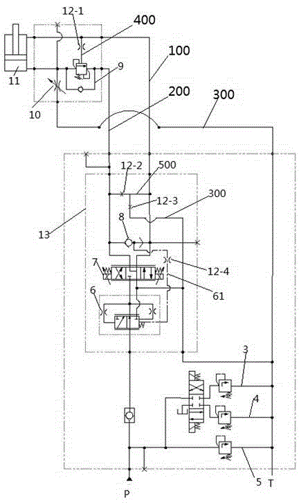
[0024] Such as figure 2 Shown, a kind of embodiment of piston elevating mechanism, the piston elevating mechanism in this embodiment comprises piston cylinder 11, is connected with piston rod on the piston of piston cylinder 11, and the inner chamber of piston cylinder 11 is divided into rod cavity and chamber by piston. The rodless chamber also includes a hydraulic control device for driving the piston to reciprocate. The hydraulic control device includes a first oil circuit 100 corresponding to the rod chamber of the piston cylinder 11 and a first oil passage 100 communicated with the rodless chamber of the piston cylinder 11. The second oil passage 200, where the first oil passage and the second oil passage communicate with the speed compensation module 13, where the two working ports of the proportional reversing valve 7 in the speed compensation module 13 are respectively connected to the first oil passage The oil passage 100 and the second oil passage 200 communicate, w...


PUM


Abstract

The invention provides a piston lifting mechanism and a hydraulic control device thereof. The hydraulic control device comprises a first oil way and a second oil way, the first oil way is used for communication with a rod cavity of a piston cylinder in the piston lifting mechanism, and the second oil way is used for communication with a rodless cavity of the piston cylinder in the piston lifting mechanism. The second oil way is provided with a balance valve, the balance valve is provided with two operation ports and a control oil port, the two operation ports are in butt-joint communication with the second oil way, and the control oil port is communicated with the first oil way through a hydraulic control oil way with a damping hole section. When the hydraulic control device is applied to the piston lifting mechanism, a piston moves towards the rodless cavity, namely the piston moves downwards, hydraulic oil in the rodless cavity flows out slowly due to slow and stable opening of the balance valve, the piston moves slowly under the action of a load and high-pressure oil in the rod cavity, and high lifting stability is realized.

Description

technical field [0001] The invention relates to a piston lifting mechanism and a hydraulic control device thereof. Background technique [0002] The piston lifting mechanism in construction machinery and other industrial fields realizes the external work of the lifting mechanism by controlling the reciprocating lifting of the piston. The piston lifting mechanism is mostly driven by hydraulic pressure, such as figure 1 As shown, the commonly used hydraulic control device for driving the piston up and down includes a reversing valve 103 having an oil inlet P, an oil return port T, a working port A, and a working port B. The reversing valve 103 is a two-position four-way reversing valve. The oil inlet of the reversing valve 103 is connected with the oil pump, the oil outlet T of the reversing valve 103 is connected with the oil tank, and the working port B of the reversing valve 103 is connected with the rod cavity of the piston cylinder 106 through the first oil passage 107 t...

Claims


Application Information

Patent Timeline
IPC IPC(8): F15B11/05F15B13/02F15B13/04
CPCF15B11/05F15B13/02F15B13/04F15B2211/3053
Inventor 张晓伟王征宇乔永强孙青锁任小博鲍雷
Owner 凯迈(洛阳)测控有限公司
Why Eureka
Try Eureka