Shear fork-type ejection mechanism

A jacking mechanism, scissors and forks technology, applied in the direction of lifting frame, lifting device, etc., can solve the problems of poor stability, and achieve the effects of easy maintenance and assembly, good lifting stability, and good application prospects

Active Publication Date: 2018-11-27
ANHUI RUIXIANG IND
View PDF5 Cites 0 Cited by
  • Summary
  • Abstract
  • Description
  • Claims
  • Application Information

AI Technical Summary

Problems solved by technology

The jacking mechanism in the prior art has poor stability during operation

Method used


Image

  • Shear fork-type ejection mechanism
  • Shear fork-type ejection mechanism

Examples


Embodiment Construction

[0020] The specific implementation manner of the present invention will be described in further detail below by describing the embodiments with reference to the accompanying drawings.

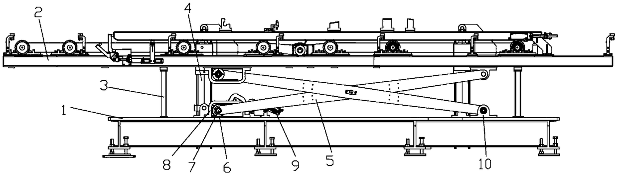
[0021] This scissors fork type jacking mechanism of the present invention, as figure 1 As shown, it includes the base 1, and also includes the jacking frame 2 set above the base 1 driven by the lifting cylinder 4. 5.

[0022] Such as figure 1 As shown in , one side of the scissors and fork assembly 5 is a fixed end, and one side is a sliding end. The upper end and the lower end of the fixed end of the scissor-fork assembly 5 are respectively hinged on the jacking frame 2 and the base 1 through the hinge seat 10;

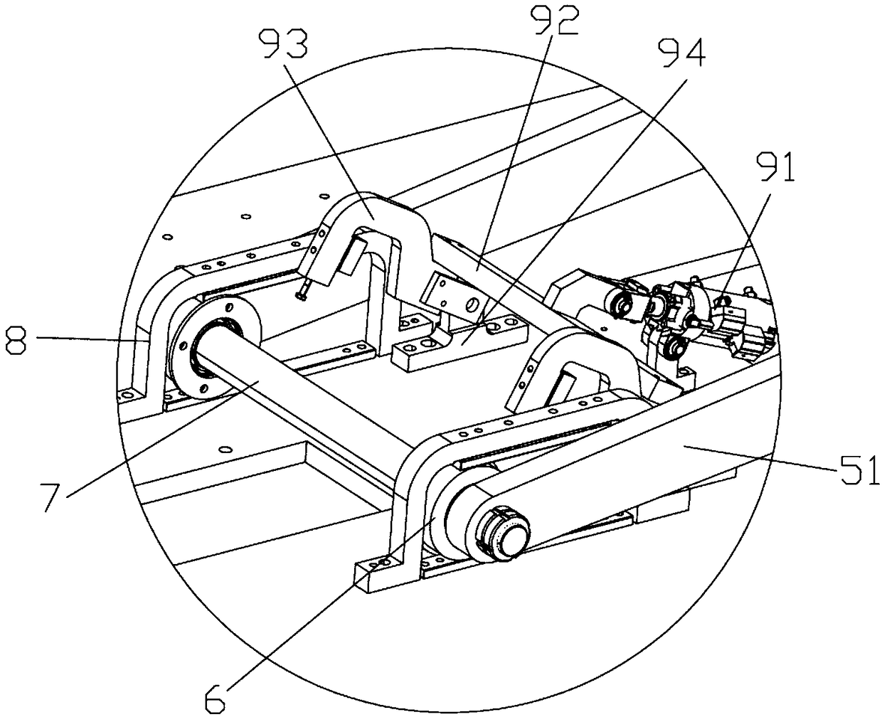
[0023] In the present invention, the scissor fork assembly 5 includes two cross-connected jacking rods 51, and the two jacking rods 51 are rotatably connected by a pin shaft to form a scissor-shaped cross-connected structure. Stability during the process, stably supporting the lif...


PUM


Abstract

The invention discloses a shear fork-type ejection mechanism which comprises a base. The shear fork-type ejection mechanism is characterized by comprising an ejection frame connected with and driven by a lifting cylinder and arranged above the base, wherein a workpiece is arranged on the ejection frame, and a shear fork assembly is arranged between the ejection frame and the base. The shear fork-type ejection mechanism is simple in structure, good in lifting stability, convenient to maintain and assemble and has better application prospect.

Description

technical field [0001] The invention belongs to the technical field of automobile tooling, and more specifically relates to a scissor-fork type jacking mechanism. Background technique [0002] In the process of automobile assembly and welding, it is often necessary to position and install the assembly on a specific tooling, and the tooling drives the assembly to lift or lower to a suitable height to meet further assembly and transportation needs. The jacking mechanism in the prior art has poor stability during operation. Contents of the invention [0003] The object of the present invention is to solve the problems existing in the prior art and provide a scissor-fork jacking mechanism with simple structure and good jacking stability. [0004] In order to achieve the above object, the technical solution adopted by the present invention is: the provided scissor-fork type jacking mechanism includes a base, and is characterized in that it also includes a jacking frame that is...

Claims


Application Information

Patent Timeline
IPC IPC(8): B66F7/08B66F7/28
CPCB66F7/065B66F7/08B66F7/28
Inventor 吴守军程春霞刘泽军
Owner ANHUI RUIXIANG IND
Why Eureka
Try Eureka